Saturday, August 31, 2013

0 Comments
Posted in Arrangement, Art, Business

LED Torch using NSI45090JDT4G Constant Current Regulator

A very simple LED torch can be designed using the NSI45090JDT4G adjustable constant current regulator (CCR) designed by ON Semiconductor ,using extreme few external components. NSI45090JDT4G device is designed to provide a cost effective solution for regulating current in LEDs. This Constant current regulator is based on patent-pending Self-Biased Transistor (SBT) technology and regulates current over a wide voltage range. It is designed with a negative temperature coefficient to protect LEDs from thermal runaway at extreme voltages and currents.

LED Torch Circuit Diagram


LED Torch using NSI45090JDT4G Constant Current Regulator

The Radj pin allows Ireg(SS) to be adjusted to higher currents by attaching a resistor between Radj (Pin 3) and the Cathode (Pin 4). The Radj pin can also be left open (No Connect) if no adjustment is required.The maximum current that can be adjusted using this chip is around 160 mA , and the maximum input voltage is around 45 volts The D1 from the circuit shown here is used for reverse battery protection .

Bellow you can see how simple is to design a circuit using this chip ( all data shown bellow are for this schematic ) .
LED’s = ((Vin − QX VF − D1 VF)/LED VF)
Example: Vin = 12 Vdc, QX VF = 3.5 Vdc, D1VF = 0.7 V
LED VF = 2.2 Vdc @ 30 mA
(12 Vdc − 4.2 Vdc)/2.2 Vdc = 3 LEDs in series.

Friday, August 16, 2013

0 Comments
Posted in Arrangement, Art, Business

Sub Woofer and Controller Rise

Sub woofers are popular, with home theater being of the driving forces. However, a nice sub adds considerably to normal hi-fi program material, & so if it is predictable & has nice response characteristics.

 all of sub woofers use a immense speaker driver in a immense box, with tuning vents & all the difficulties (& vagaries) that conventional operation entails. By conventional, I mean that the speaker & cabinet are operated as a resonant technique, using the Thistle-Small parameters to get a box which will (if everything works as it ought to) provide excellent performance.

Completed Prototype

A fast word is warranted here, to let you decide if the speaker you have will actually work in a little sealed enclosure. The EAS principle will permit any driver to extend to twenty Hz or even lower. A lovely fast check is to stick the speaker in a box, and drive it to 100W or so at twenty Hz - you ought to see lots of cone movement, a few things will rattle, but you should not actually listen to a tone. A "bad" speaker will generate 60 Hz (third harmonic) - in the event you dont listen to anything, the speaker will work in an equalized sub.

If a tone is audible, or the speaker shows any signs of distress (such as the cone breaking up with appropriate terrible noises), then the driver cannot be used in this manner. Either discover a different driver, or use a vented enclosure.

Before you can build your own EAS box, you will require to pick an appropriate driver, using the above as a guide. Cone tour will be high at the lowest frequencies, so the speaker needs to be able to high power, lovely tour, & of reasonable size (there is no substitute for cone area for moving air at low frequencies). I am using a 380mm (15") driver, but smaller drivers (say 300mm - 12") can be used, or even a bigger number of smaller drivers. I have also had excellent results with a single 300mm driver, which has lower sensitivity (as would expect) but is perfectly adequate for normal usage.


The check methods I used are applicable to any combination, but in general I recommend either a single giant driver or a pair of (say) 300mm units. The next hurdle is the amplifier needed to drive the speaker. This is not trivial. If the selected driver has a sensitivity of 93dB / W @ one metre, then you can safely assume that the efficiency will be less than this below resonance, by a factor of possibly 6dB or more. In case you are used to driving a sub with 100W, this means that you have increased the power to 400W - although this is an over-simplification.

If they are to operate the sub from 60Hz (my aim from the outset), they will increase the power by 12dB for each octave, so if 20W is necessary at 60Hz, then at 30Hz this has increased to 320W, & at 15Hz, you will require over 5kW.

Fortunately, the reality is a tiny different, & 400W or so will be over sufficient for a powerful process, due chiefly to the fact that the energy content in the low bass region is not normally all that great. (Although some program material may have high energy content, in general this is not the case). The EAS process augments the existing process, which is allowed to roll off naturally - contrast this with the normal case, where a crossover is used to separate the low bass from the main process, so existing speaker capability is lost.

The box I built is made from 25mm (1") MDF (Medium Density Fiberboard), & filled with fiberglass. Apart from the fact that it is very heavy (which is a lovely thing, because it desires to walk with low frequencies), the cabinet is acoustically dead, with no resonances in the low frequencies at all ( unlike my house & furniture, dammit !). The woofer is recessed in to the baffle, & sealed with weather sealing foam. When attaching the speaker, do NOT use wood screws, or any other screw in to the MDF. I used "Tee" nuts. I have no idea what they are called elsewhere in the world, but they look like this

TEE NUT

The middle is tapped, and accepts a metal thread screw, and the small spikes mean that you must drill a hole, and hammer in the Tee nut. In case you use a screw through the hole and screwed lightly in to the Tee nut, you can hold it in place as you bash away at it, and can also see that it is straight when you are done. make sure that the finish of the screw doesnt stick out the finish, or you will seldom remove it again after the hammering! I recommend that you lock the tee nut in to place with some construction adhesive (dont get any in the threaded section) so they dont fall out while you are installing the speaker.

The EAS Controller
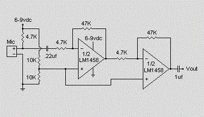
The controller is (actually very) simple, & the circuit is shown in Figure one. An input buffer ensures that the input impedance of the source does not affect the integrator performance, & allows summing of left & right channels without any crosstalk. The output provides a phase reversal switch, so that the sub can be properly phased to the remainder of the process. If the mid-bass disappears as you advance the level control, then the phase is wrong, so switch to the opposite position.

Figure 1 - The Original EAS Filter / Controller

It turns out that the controller can be simplified, but there is no point. While the dual pot appeared like a lovely suggestion when I built my unit, it actually only changes the gain. Now, having experimented some more, this is an excellent thing, since it means that the level through the controller can be set to make positive that there is no distortion - there can be a immense amount of gain at low frequencies, & if the gain is high, distortion is assured!

The integrators (U1B & U2A) include shelving resistors (R6 & R9), & the capacitor / resistor networks (C1-R4, C3-R7) be positive that signals below 20Hz are attenuated. In case you dont require to go that low, then the worth of the caps (or the resistors R4 & R7) can be reduced. I used four.7uF caps, & these are non-polarized electrolytic - a high value was needed to keep the impedance low to the integrators. I originally included the dual pot (VR1) to permit the upper frequency roll off to be set - however it does no such thing (as described above). The final output level is set with VR2, which may be left out if your power amp has a level control.

It is OK to substitute different op amps, but there is tiny reason to do so. Any substitution tool ought to be a FET input op amp, or DC offset may be an issue. Do not be tempted to make use of a DC coupled amp. If the you are planning to make use of is DC coupled, the input ought to be isolated with a capacitor. Pick a value to give a -3dB frequency of about 10Hz, as this will have tiny effect on the low frequency response, but will help to attenuate the subsonic frequencies.

The unity gain range (using a 20k pot as shown) is from 53Hz to 159Hz. This ought to be sufficient for most systems, but if desired, the resistors (R5 & R8) can be increased in value to 22k, or you can select a bigger value pot. Using 22k resistors & the 20k pot will give a range from 36Hz to 72Hz.

To permit lower frequencies, you can increase the 100k shelving resistors (R6 and R9) to 220k, and increase the high pass capacitors (four.7uF) with 10uF (or R4 & R7 may be increased - a maximum of four.7k is recommended). This will give a turnover frequency of around 8Hz, but expect to make use of much more power, as there will likely be significant sub-sonic energy that will generate huge cone excursions with no audible benefit.

The input must be a standard full range (or for a stampeded method, the whole low frequency signal). Do not use a crossover or other filter before the EAS controller. For final modification, and to integrate the method in to your listening room, I recommend the constant-Q equalizer. The final result using this is extraordinarily nice - I have flat in-room response to 20Hz!

For the power supply, use the in anything else will provide +/-15V at a few Milli amps. My supply is not even regulated, & the whole method is as close to noiseless as you will listen to (or not listen to). Construction is not critical - I built mine on a piece of Overboard (perforated prototype board), & managed to fit everything (including the power supply rectifier & filter) on a piece about 100 x 40 millimeters with room to spare.

The EAS method is surprisingly simple to set up with no instrumentation. Of coursework in case you have an SPL meter & oscillator you can also confirm the settings with measurements. Keep in mind that the room acoustics will play havoc with the results, so unless you require to drag the whole method outside, setting by ear might be the simplest. Even in case you did get it exactly right in an anechoic surroundings, this would alter one time it was in your listening room anyway.

It takes a small experimentation to get right, but is surprisingly simple to do. When properly set, a check track (or bass guitar) ought to be smooth from the highest bass note to the lowest, with no gross peaks or dips. Some are inevitable because of room resonances & the like, but you will discover a setting that sounds "right" with small difficulty.

Performance Of My Prototype
I measured 80dB SPL at one meter in my workshop (sub-woofer perched on a chair in more or less the middle of the space) with at 25Hz & 70W. This improved dramatically when the unit was installed in the listening room, but as I said earlier, there is usually not a lot recorded below around 35Hz. The longest pipe on the organ is usually about 16Hz, but larger pipes still may be used. It was found necessary to cease group of diapasons (able to 8Hz) in the famous Sydney Town Hall organ because when they were used, the very low frequency caused building destroy.

A couple of orchestral recordings revealed traffic (or perhaps underground railway) rumble that I was unaware of before (however this was before it was set correctly, and the bass was a tad louder than needed). One time set up properly, its presence is unobtrusive - except I now have about and a half octaves of additional bottom finish.

I finally decided on a 20Hz maximum frequency (-3dB), and this is reflected in the part values shown in Figure one. The actual roll-over frequency is 16.5Hz, after which the output is attenuated at about 12dB / octave (see Figure two). Without the roll off capacitors, the gain would be 20dB at 20Hz. Unity gain frequencies are about 4Hz and 63Hz with the 20k pot(s) centered.

Figure 2 - Frequency Response of EAS Controller

awesome Australian readers may recognize the woofer brand in the picture (Figure three) of my done unit. The compact size of the box can be seen from the fact that there is tiny spacing around the speaker itself, and most of what is there is the top and sides - I used 25mm MDF, so it makes the outside of the box a bit bigger than the inside. Outside dimensions are 470W x 450H x 410D (18 1/2"W x 17 1/2"H x 16"D), which gives a capacity of 60 liters (about two.1 ft³ - excluding the internal space occupied by the speaker. I think you would agree that this is a small box indeed for a 380mm loudspeaker that performs down to 15Hz.

Figure 3 - Photo of Completed EAS Cabinet


Overall, I would must say that I doubt that any conventional design would be as compact, or would have such clarity & solidarity. Being a sealed box, there is not of the "waffle" that ported designs often give, & the speaker is protected against excessive tour by the air pressure in the box itself (below the cutoff frequency, anyway).

The bottom finish in my technique is now staggering. It is rock solid, & absolutely thunders when called on. The 400W amp is over sufficient for the job, thinking about its to keep up with a biamped main technique able to high SPL (up to 120dB at my listening position). In fact a fast check indicates that 200W would have been (but . better to have it & not require it than require it & not have it).

The fact that the EAS design augments the existing speakers than taking over from them with a crossover goes a long way towards ensuring the power requirements do not get out of hand. As an added benefit, I have found that I get the same aural sensation at much lower SPLs - I can listen happily at 90dB, but it sounds much louder. I may even listen to the phone ring while listening now !
All in all, I feel it is unlikely that anything other than an isobaric enclosure could give the same performance for a box size even close to the EAS box,& even then would be limited to about 35Hz. Added to this is the unpredictable combined response of the main speakers and the sub, which is not an Problem with this design. With an EAS system, more power is necessary than a standard design, but for plenty of people, power is less costly than space.

Thursday, August 15, 2013

0 Comments
Posted in Arrangement, Art, Business

Simple Proximity Detector Alarm Circuit

This is a simple proximity switches with IC 4049th The IC4049 is a bipolar monolithic integrated circuit for use in metal-detection system / proximity sensing applications IC4049 includes an oscillator constituted by an external parallel resonant tank circuit and a feedback resistor connected 2-5 The internal oscillator operates near the resonant frequency of the tank is brought circuit.As a metal object near the coil begins to decrease the amplitude of the voltage across the tank gradually.

Proximity Detector & Alarm Circuit


If the envelope of the oscillation a certain level, the greater the resistance the greater the travel distance.Detection-point range with a high Q coil.Maximum possible range can be achieved with a well extended to 1-inch drive circuit. Only So this circuit, the tuning circuit to a certain range.

For making it easy to a metal coil at the desired distance (1 inch) square and adjust the resistance, C1 and C2 (make Pin2 or 5) one of the outputs in the state change.

Wednesday, August 14, 2013

0 Comments
Posted in Arrangement, Art, Business

Ethernet Crossover Cable Wiring

Ethernet Wiring on Connectlink Wireless   Ethernet Wiring Diagram
Connectlink Wireless Ethernet Wiring Diagram.


Ethernet Wiring on Tech Info   Lan Wiring And Pinouts
Tech Info Lan Wiring And Pinouts.


Ethernet Wiring on Ethernet Crossover Cable Wiring
Ethernet Crossover Cable Wiring.


Ethernet Wiring on The Difference Between Straight Through  Crossover  And Rollover
The Difference Between Straight Through Crossover And Rollover.


Ethernet Wiring on Ethernet Wiring
Ethernet Wiring.


Ethernet Wiring on Tech Info   Lan Wiring And Pinouts
Tech Info Lan Wiring And Pinouts.


Ethernet Wiring on Cat 5 Ethernet Cable Standards   Pin Out Assignments
Cat 5 Ethernet Cable Standards Pin Out Assignments.


Ethernet Wiring on Cat6 568 A Wiring Diagram
Cat6 568 A Wiring Diagram.


Ethernet Wiring on Qvlweb  Ethernet Wiring And Loop Back
Qvlweb Ethernet Wiring And Loop Back.


Ethernet Wiring on Diy 9   Ethernet Wiring Diagram
Diy 9 Ethernet Wiring Diagram.


0 Comments
Posted in Arrangement, Art, Business

Wireless mains voltage tester

Description.
This circuit can be used to test whether mains voltage is present or not without having electric contact with mains line. The CMOS IC CD4033 is the heart of this circuit. The CD4033 consists of a 5 stage decade Johnson counter and an output decoder for converting the Johnson code to a 7 segment decoded output for driving 7 segment LED display. A 10cm long insulated copper wire connected to the clock pin (pin1) of the IC serves as the sensor. The sensor wire has to be placed in the vicinity of the mains wire to be tested. When there is no voltage in the mains line, no voltage will be induced in the sensor wire and the display will show a random digit. When there is voltage in the mains line, a small voltage will be induced in the sensor wire due to electromagnetic induction and this voltage is sufficient enough to clock the CMOS IC CD4033. Now the display will count from zero to nine and repeat.
Circuit diagram.
wireless mains indicator
Notes.
  • The circuit can be assembled on a Vero board.
  • Use 9V PP3 battery for powering the circuit.
  • Use a 10cm insulated wire as the sensor.
  • The IC must be mounted on a holder.
  • Switch S1 can be a miniature ON/OFF switch.

Tuesday, August 13, 2013

0 Comments
Posted in Arrangement, Art, Business

Escape and Emergency Lighting

In accordance with the Fire Precautions Act 1971 and the Health and Safety at Work Act 1974, BS EN 1838 : 1999 Code of practice for the emergency lighting of premises must followed with minimum standards to achieve the safety target.
It is important matter for safety precaution when emergency happen such as fire,explosive,electrical disaster or etc.This system provide the solution for escape to the assembly point in safety and proper ways.


For each country it have their own Act,regulation and code of practice.Basically it quite similar and have additional items depend on their application and suitable with their country.
This time i want share about basic knowledge for term of emergency lighting system.Before we install or design the new system,firstly we need to understand the definitions of terms that commonly used for escape and emergency lighting system.

Monday, August 12, 2013

0 Comments
Posted in Arrangement, Art, Business

Install Electrical Wiringdoityourself

Basic Electrical Wiring on The Basics Of Household Wiring Dvd   Electrical Online
The Basics Of Household Wiring Dvd Electrical Online.


Basic Electrical Wiring on Types Of Electrical Wiring   Hometips
Types Of Electrical Wiring Hometips.


Basic Electrical Wiring on Gfci Outlet Wiring Diagram   Pdf  55kb
Gfci Outlet Wiring Diagram Pdf 55kb.


Basic Electrical Wiring on The Most Basic Principles Of The Wiring In Your Home Are Simple  The
The Most Basic Principles Of The Wiring In Your Home Are Simple The.


Basic Electrical Wiring on How To Install Electrical Wiring   Doityourself Com
How To Install Electrical Wiring Doityourself Com.


Basic Electrical Wiring on Alternative Wiring Diagram   Pump On Timer  Solarattic S Solar
Alternative Wiring Diagram Pump On Timer Solarattic S Solar.


Basic Electrical Wiring on Electrical Circuit Diagram Related Posts Wiring And Connectors
Electrical Circuit Diagram Related Posts Wiring And Connectors.


Basic Electrical Wiring on Here Is A Basic Wiring Diagram For A Light Box
Here Is A Basic Wiring Diagram For A Light Box.


Basic Electrical Wiring on Wiring A Light Switch For A Ceiling Light Diy Project
Wiring A Light Switch For A Ceiling Light Diy Project.


Basic Electrical Wiring on Electrical Wiring Diagrams
Electrical Wiring Diagrams.


Sunday, August 11, 2013

0 Comments
Posted in Arrangement, Art, Business

Build a Diode Cmos Stabilizer Circuit Diagram

The simple diode network can stabilize the voltage supplied to CMOS circuitry from a battery. D1 and D2 must have a combined forward-voltage drop of about 1.5 V. And D3 is an LED with a forward-voltage drop of about 1.7 V. The table shows the network`s output voltage as the battery`s voltage declines.

 Diode Cmos Stabilizer Circuit Diagram


Diode Cmos Stabilizer Circuit Diagram

Saturday, August 10, 2013

0 Comments
Posted in Arrangement, Art, Business

LED light flasher


This is a good and simple circuit to flash one or more LED lights.  The circuit uses a NE 555 small IC. This IC is very common and easy to obtain from any electronic components shop.  As you can see in the circuit diagram we have used 10uF capacitor to control the flash speed of the LEDs. If you want to increase the speed simply put a higher value of a capacitor in place of 10uF.

Also you can increase the number of LED lights in parallel way. The maximum we recommend is 18 lights. Use PCB board to build this and supply six volts. Do not supply more than six as it can damage the your components as well as LED bulbs.


Friday, August 9, 2013

0 Comments
Posted in Arrangement, Art, Business

Condenser Pre Amplifier LM 1458

This is a simple preamplifier circuit for electret condenser microphone.
using a LM1458 dual op amp IC. The circuit takes the audio signal rom the condenser microphone and amplifier it, so you can use the microphone as the input to some device which wouldn’t normally accept microphone level signals .

Condenser Pre Amplifier


Schematic Circuit of Microphone Electret

Condenser Pre Amplifier


The circuit requires a 6-9 volt supply. Output of the microphone amplifier can be made variable by connecting a 10kΩ potentiometer . Circuit’s gain can be increased by men perbesar the value of 47K, depending on the input sensitivity of the main amplifier system. The microphone should be housed in a small round enclosure.


List componet of condenser pre-amp mic circuit

Q1,Q2    : LM1458 Op-Amp

R1,R2,R3 : 4.7k ohm resistor

R4, R5   : 10k ohm resistor

R6,R7    : 47k ohm resistor

C1,      : 0.22uF ceramic capacitor

C2       : 1uF ceramic capacitor


Absolute maximum ratings of LM 1458 IC

Supply Voltage               :  ±18V

Power Dissipation            : 400 mW

Differential Input Voltage   : ±30V

Input Voltage                : ±15V

Output Short-Circuit Duration: Continuous

Operating Temperature Range  : 0°C to +70°C

Storage Temperature Range    : −65°C to +150°C

Lead Temperature             :(Soldering, 10 sec.) 260°C
0 Comments
Posted in Arrangement, Art, Business

High voltage Power supply Circuit Diagram

High voltage Power supply Circuit Diagram. A 6 V battery can provide 100-150 Vdc center-tapped at a high internal impedance (not dangerous though it can inflict an unpleasant jolt). A 6.3 V transformer is connected in reverse with a transistor used in a Hartley oscillator configuration. The frequency of operation may be controlled by varying the value of the 10 ohm resistor.The 10 µ¥ capacitor must have a working voltage of at least 250 Vdc .

 High voltage Power supply Circuit Diagram


High voltage Power supply Circuit Diagram

Thursday, August 8, 2013

0 Comments
Posted in Arrangement, Art, Business

12 V battery charger with PUT

A
short-circuit proof battery charger will provide an average charging
current of about 8A to a 12V lead-acid storage battery. The Charger
circuit has an additional advantage, it will not function nor will it be
damaged by improperly connecting the battery to the circuit. With 220V
at the input , the circuit comences to function when the battery is
properly attached.

simple battery charger
The
battery provides the current to charge the timing capacitor C1 used in
the PUT relaxation oscillator.When C1 charges to the peak point
voltage the PUT , the PUT fires turning the SCR on , which in turn
applies charging current to the battery. As the battery charges , the
battery voltage increases slightly which increases the peak point
voltage of the PUT. The voltage on C1 increases until the zener voltage
of D1 is reached , which clamps the voltage on C1 , and thus prevents
the PUT oscillator from oscillating and charging ceases. The maximum
battery voltage is set by potentiometer R2 which sets the peak point
firing voltage pf the PUT . In the circuit shown , the charging voltage
can be set from 10 V to 14 V - the Lower limit being set by D1 and the
upper limit by T1.


Part List :

Resistor
R1 = 10K
R2 = 50K trim
R3 = 47K
R4 = 1K

Capacitor
C1 = 0.1uF

Diode , SCR , PUT
B1 = MDA990-1
D1 = 1N5240 10V
SCR = 2N5164
PUT = MPU131

Transformer , Inductor
T1 = Stepdown 220V to 14V
T2 = 11Z12 1:1 

Wednesday, August 7, 2013

0 Comments
Posted in Arrangement, Art, Business

8 to 18 volts TDA2005 Power Amplifier

This time, there is a series of audio amplifer 20W as well, but using IC TDA 2005 as a series of his base amplifier. The series of 2x20 Watt Audio Power Amplifier using TDA2005 can you see in the picture below.


TDA2005 2 X 20 Watt Power Amplifier

Technical Data:
Performance of TDA2005M: (for this circuit); At 4.14 V supply voltage: 2 x 20 watts (stereo) into 4 Ohms.
Distortion: Approx. 0.2% at 4 Watts into 4 ohm load.
Frequency Range: Approx. 20 Hz to 22 KHz.
Input Sensitivity: Approx. maximum 150 mV rms. .
Power supply: + 8 to 18 volts, approx. 3.5 Amps maximum per channel.
source [link] 

Tuesday, August 6, 2013

0 Comments
Posted in Arrangement, Art, Business

Latch Switch 2

This circuit uses a Silcon Controlled Rectifier (SCR) as a latch switch. Once enabled it can only be turned off by pressing S2 or power is removed from the circuit.

Latch Switch 2 Circuit Diagram


Circuit Notes:
The load is represented by the 1k resistor and orange LED, although the C106D can handle much larger loads. Once the On switch is pressed, the SCR receives a voltage on its gate terminal and goes into forward conduction and conducts current through its anode and cathode terminals. This current remains to flow even when the on switch is released, so the LED remains lit.

The load can only be turned off by pressing the Reset switch which is a Push-to-Break non-latching push switch. Note that reset switch must be able to handle the full load currents and voltage.

Monday, August 5, 2013

0 Comments
Posted in Arrangement, Art, Business

Simple 500W 12V to 220V Inverter


This is a 500W DC-to-AC inverter circuit diagram which produces an AC output at line frequency and voltage. 12VDC to 220V 50Hz inverter circuit will power 220V or 110V appliances from 12V car battery. The circuit is easy to make and is low cost. Use proper transformer. The output (in watts) is up to you by selecting different power rating transformer and power transistor rating. If you load electronic device which require 120V AC, then use transformer with 120V in output.link

Sunday, August 4, 2013

0 Comments
Posted in Arrangement, Art, Business

10Mhz to 1 MHz Frequency Converter

10Mhz to 1 MHz Frequency Converter Circuit

10Mhz to 1 MHz Frequency Converter

Part ListIC1 7404 = 1
IC2 7490A = 1
R 1 K = 2
R 3.3 K = 1
C Trim Polymer 39 pF = 1
C Electrophoresis 4.7 uF 16V = 1
C Milar 47 nF 16 V = 1
C Milar 10 nF 16 V = 1
C Ceramic 68 pF 50 V = 1 
0 Comments
Posted in Arrangement, Art, Business

Gibson RD Artist Guitar circuit schematic with explanation


The following diagram is the schematic of Gibson RD Artist bass guitar

Circuit Notes:

  1. Both compression and expansion effects are determined by the lead pickup output only.
  2. I and O in the design diagram refer to inner and outer connections for the specific plug / jack.
  3. P and J in the design diagram refer to plugs and jacks respectively.
  4. The two green wires connecting to the P1- (5,6) are signal grounds. P1-8 being used for plug priority sensing.

Gibson RD Artist guitar schematic diagram designed by Fabian P Hartery

Download the schematic in PDF file:
» Download Link

Saturday, August 3, 2013

0 Comments
Posted in Arrangement, Art, Business

Gaza Drone Crasheshamas Presents Photosisrael Newsynetnews

Drone Aircraft on Us Drone Aircraft Picture On Visualizeus
Us Drone Aircraft Picture On Visualizeus.


Drone Aircraft on Weapon Of Choice     A Us Air Force Mq 9 Reaper Drone Aircraft
Weapon Of Choice A Us Air Force Mq 9 Reaper Drone Aircraft.


Drone Aircraft on Gaza  Idf Drone Crashes  Hamas Presents Photos   Israel News  Ynetnews
Gaza Idf Drone Crashes Hamas Presents Photos Israel News Ynetnews.


Drone Aircraft on Drone Aircraft On Missions In Afghanistan And Other War Zones  Xinhua
Drone Aircraft On Missions In Afghanistan And Other War Zones Xinhua.


Drone Aircraft on Drone Aircraft In Eastern Iran  A Military Source Told State
Drone Aircraft In Eastern Iran A Military Source Told State.


Drone Aircraft on Predator Drone  Img  Nationalyemen
Predator Drone Img Nationalyemen.


Drone Aircraft on Drone Aircraft Recentlyincorporated Into The Series  Terminator  The
Drone Aircraft Recentlyincorporated Into The Series Terminator The.


Drone Aircraft on Drone Aircraft  Kopie
Drone Aircraft Kopie.


Drone Aircraft on Chinese Drone
Chinese Drone.


Drone Aircraft on Still Scrambling To Explain Why And How They Lost A Drone Aircraft
Still Scrambling To Explain Why And How They Lost A Drone Aircraft.


Thursday, August 1, 2013

0 Comments
Posted in Arrangement, Art, Business

Switch Timer Circuit For Bathroom Light

This 9-minute timer switch can be used to control the light in a toilet or bathroom. The timer is started by pushing S1 and stopped by pushing S1 again. If you forget to turn it off, the controlled light will go off after nine minutes. If you need the light on continuously non-stop, you need to press S1 (turn on) and then S2 (cancellation of timer) within 9 minutes and in this case the light will be on until you switch it off with S1.
Circuit diagram:
switch-timer-circuit-diagram
Switch Timer For Bathroom Light
IC1 is a is 4013 dual flip-flop. Flip flop IC1a is toggled on and off by switch S1 and it controls the relay which is switched by FET Q2. IC1a controls IC1b which is connected as an RS flipflop to enable or disable IC2, a 4060 oscillator/divider. This has its timing interval set by the components at its pins 9, 10 & 11. The relay should have 250VAC mains-rated contacts and these are connected in parallel with an existing wall switch.
Author: Rasim Kucalovic - Copyright: Silicon Chip Electronics

    Total Pageviews