Showing posts with label amplifier. Show all posts

Thursday, January 9, 2014

0 Comments
Posted in Arrangement, Art, Business

Simple 4 Channel Video Amplifier using NJM2582

A very simple 4 channel video amplifier electronic circuit project can be designed using NJM2582 ic suitable for video applications with SCART connector . Design of the circuit is very simple and require few external electronic parts .

Circuit diagram :

4 channel-video-amplifier Circuit Daigram

Simple 4 Channel Video Amplifier Circuit Diagram

Some features of the NJM2582 are : Operating Voltage ±5V, +5V, +11V ; 6input 4output , 2input 1output Video SW , Internal LPF , 6dB Amplifier , Internal 75Ω Driver Circuit , DC output for SCART (FUNCTION SW, BLANKING) .

Sunday, December 22, 2013

0 Comments
Posted in Arrangement, Art, Business

Mini Box 2W Amplifier with Bass Boost Switch

This amplifier was designed to be self-contained in a small loudspeaker box. It can be feed by Walkman, Mini-Disc, iPod and CD players, computers and similar devices fitted with line or headphone output. Of course, in most cases you will have to make two boxes to obtain stereo.
Mini-Box 2W Amplifier Circuit Diagram
The circuit was deliberately designed using no ICs and in a rather old-fashioned manner in order to obtain good harmonic distortion behavior and to avoid hard to find components. The amplifier(s) can be conveniently supplied by a 12V wall plug-in adapter. Closing SW1 a bass-boost is provided but, at the same time, volume control must be increased to compensate for power loss at higher frequencies.

In use, R9 should be carefully adjusted to provide minimal audible signal cross-over distortion consistent with minimal measured quiescent current consumption; a good compromise is to set the quiescent current at about 10-15 mA. To measure this current, wire a DC current meter temporarily in series with the collector of Q3.

Parts:


P1_____________10K Log.Potentiometer
R1,R2__________33K 1/4W Resistors
R3_____________33R 1/4W Resistor
R4_____________15K 1/4W Resistor
R5,R6___________1K 1/4W Resistors
R7____________680R 1/4W Resistor
R8____________120R 1/2W Resistor
R9____________100R 1/2W Trimmer Cermet
C1,C2__________10µF 63V Electrolytic Capacitors
C3____________100µF 25V Electrolytic Capacitor
C4,C7_________470µF 25V Electrolytic Capacitors
C5_____________47pF 63V Ceramic Capacitor
C6____________220nF 63V Polyester Capacitor
C8___________1000µF 25V Electrolytic Capacitor
D1___________1N4148 75V 150mA Diode
Q1____________BC560C 45V 100mA PNP Low noise High gain Transistor
Q2____________BC337 45V 800mA NPN Transistor
Q3____________TIP31A 60V 4A NPN Transistor
Q4 ___________TIP32A 60V 4A PNP Transistor
SW1___________SPST switch
SPKR__________3-5 Watt Loudspeaker, 8, 4 or 2 Ohm impedance

Wednesday, October 2, 2013

0 Comments
Posted in Arrangement, Art, Business

MINI AUDIO AMPLIFIER ELECTRONIC CIRCUIT DIAGRAM

MINI AUDIO AMPLIFIER ELECTRONIC CIRCUIT DIAGRAM

The 8k2 across the 47u sets the emitter voltage on the BC 547 and this turns it on. The collector is directly connected to the base of a BC 557, called the driver transistor. Both these transistors are now turned on and the output of the BC 557 causes current to flow through the 1k and 470R resistors so that the voltage developed across each resistor turns on the two output transistors. The end result is mid-rail voltage on the join of the two emitters. The two most critical components are 8k2 between the emitter of the first transistor and 0v rail and the 470R resistor.

Saturday, September 28, 2013

0 Comments
Posted in Arrangement, Art, Business

Video Amplifier Circuit Diagram

The video amplifier in the diagram is a well-known design. Simple, yet very useful, were it not for the ease with which the transistors can be damaged if the potentiometers (black level and signal amplitude) are in their extreme position. Fortunately, this can be obviated by the addition of two resistors. If in the diagram R3 and R4 were direct connections, as in the original design, and P1 were fully clockwise and P2 fully anticlockwise, such a large base current would flow through T1 that this transistor would give up the ghost.

Circuit diagram:

Video_Amplifier_Circuit_Diagramw

Video Amplifier Circuit Diagram

Moreover, with the wiper of P2 at earth level, the base current of T2 would be dangerously high. Resistors R3 and R4 are sufficient protection against such mishaps, since they limit the base currents to a level of not more than 5 mA. Shunt capacitor C4 prevents R4 having an adverse effect on the amplification.

Author: L.A.M. Prins - Copyright: Elektor Electronics

Friday, September 27, 2013

0 Comments
Posted in Arrangement, Art, Business

Dual Input Combining Stereo Line Amplifier

This circuit takes two separate line-level stereo (L & R) signals and combines them into one stereo (L & R) output, thus avoiding the need to switch between two pairs of input signals. In the author’s application, it is used to feed the stereo audio from a TV receiver and a DVD player into an external amplifier. The need for the circuit arose because of a design peculiarity in the TV receiver. The TV has four A/V inputs and one A/V output. AV1-AV3 accept composite or S-video plus stereo audio inputs and these feed into the TV’s A/V output. AV4 accepts Component video (Y/Pb/Pr) plus stereo audio but unlike AV1-AV3, its audio (and video) signals are not fed to the TV A/V output. The Y/Pb/Pr input was chosen for use with the DVD player because of its superior video quality, while the audio was to be fed to an external amplifier for improved reproduction.
Circuit diagram:
stereo-line-amplifier-circuit-diagram
However, manual switching was inconvenient, hence the genesis of this design. In use, the DVD player audio is fed in parallel to TV AV4 and to one input pair of the combining amplifier, while the TV audio output feeds the other input pair. The amplifier output goes to the external audio amplifier. There is no conflict between the two audio inputs because when AV4 (DVD player) is selected, there is no TV audio output. In all other modes, the DVD player is off. As shown, the circuit has a voltage gain of 1.5 times (3.5dB) but this can be altered as required by changing the two 15kW resistors. Input impedance is 10kW and the outputs are isolated from cable and amplifier input capacitance with 47W series resistors. The circuit can be powered from a regulated 12V DC plugpack.
Author: Garth Jenkinson - Copyright: Silicon Chip Electronics

Friday, August 9, 2013

0 Comments
Posted in Arrangement, Art, Business

Condenser Pre Amplifier LM 1458

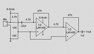
This is a simple preamplifier circuit for electret condenser microphone.
using a LM1458 dual op amp IC. The circuit takes the audio signal rom the condenser microphone and amplifier it, so you can use the microphone as the input to some device which wouldn’t normally accept microphone level signals .

Condenser Pre Amplifier


Schematic Circuit of Microphone Electret

Condenser Pre Amplifier


The circuit requires a 6-9 volt supply. Output of the microphone amplifier can be made variable by connecting a 10kΩ potentiometer . Circuit’s gain can be increased by men perbesar the value of 47K, depending on the input sensitivity of the main amplifier system. The microphone should be housed in a small round enclosure.


List componet of condenser pre-amp mic circuit

Q1,Q2    : LM1458 Op-Amp

R1,R2,R3 : 4.7k ohm resistor

R4, R5   : 10k ohm resistor

R6,R7    : 47k ohm resistor

C1,      : 0.22uF ceramic capacitor

C2       : 1uF ceramic capacitor


Absolute maximum ratings of LM 1458 IC

Supply Voltage               :  ±18V

Power Dissipation            : 400 mW

Differential Input Voltage   : ±30V

Input Voltage                : ±15V

Output Short-Circuit Duration: Continuous

Operating Temperature Range  : 0°C to +70°C

Storage Temperature Range    : −65°C to +150°C

Lead Temperature             :(Soldering, 10 sec.) 260°C

Wednesday, August 7, 2013

0 Comments
Posted in Arrangement, Art, Business

8 to 18 volts TDA2005 Power Amplifier

This time, there is a series of audio amplifer 20W as well, but using IC TDA 2005 as a series of his base amplifier. The series of 2x20 Watt Audio Power Amplifier using TDA2005 can you see in the picture below.


TDA2005 2 X 20 Watt Power Amplifier

Technical Data:
Performance of TDA2005M: (for this circuit); At 4.14 V supply voltage: 2 x 20 watts (stereo) into 4 Ohms.
Distortion: Approx. 0.2% at 4 Watts into 4 ohm load.
Frequency Range: Approx. 20 Hz to 22 KHz.
Input Sensitivity: Approx. maximum 150 mV rms. .
Power supply: + 8 to 18 volts, approx. 3.5 Amps maximum per channel.
source [link] 

Tuesday, July 9, 2013

0 Comments
Posted in Arrangement, Art, Business

Simple RF Amplifier

This RF amplifier circuit diagram is a very simple and is designed to work for 10 meters band (26 ... 30 MHz) reserved for amateurs. By making this RF amplifier small power transmitters of 200 mW, can be transformed into a power transmitters reasonable, ranging between 2 and 3 W. The circuit is very simple. Network output filter suppresses noise by at least 55 dB.

Simple RF Amplifier Circuit diagram

Amplifier is suitable for almost all types of transmissions, because of the possibility of adjusting the drain current of FETs by P1. For linear applications (AM and BLU), drain current must be adjusted to 20 mA. If is used for FM-CW, P1 will be adjusted so that no current will not flow through the drain rest. For this case, the idle current is 200 mA and between 300 mA.

Coils are made on cases with a diameter of 9 mm. Care should be taken to wound as tight turns without any space between them. Coils should be made as follows: L1 = 12 turns enamelled 0.6 mm copper, L2 and L4 = 5 turns 1 mm enamelled copper, L3 = 8 1 mm enamelled copper coils.

Wednesday, July 3, 2013

0 Comments
Posted in Arrangement, Art, Business

Audio Pre Amplifier

Simple Audio Pre-Amplifier

This simple circuit provides good gain to too audio singnals .
Use it in main of an RF oscillators to make an RF transmitter that is very sensitive to sound

Monday, May 13, 2013

0 Comments
Posted in Arrangement, Art, Business

Headphone Amplifier


High Quality unit, No need for a preamplifier So you can simply use this.try this I suppose you will enjoy with this

Parts:

P1 = 22K
R1 = 560R
R2 = 10K
R3 = 10K
R4 = 12K
R5 = 2.2R
R6 = 2.2R
R7 = 22R-1/2W
Q1 = BC337
Q2 = BC327
Q3 = BC337
Q4 = BC327
C1 = 1µF-63V
C2 = 100µF-25V
C3 = 100µF-25V
C4 = 100µF-25V
C5 = 22pF-63V
C6 = 22µF-25V
IC1 = NE5532
J1 = RCA audio input socket


Notes:

* Can be directly connected to CD players, tuners and tape recorders.
* Tested with several headphone models of different impedance: 32, 100, 245, 300, 600 & 2000 Ohm.
* Old 8 Ohm impedance headphones can be also driven, but these obsolete devices are not recommended.
* Schematic shows left channel and power supply (common to both channels).
* Numbers in parentheses show IC1 right channel pin connections.
* A correct grounding is very important to eliminate hum and ground loops. Connect to the same point the ground sides of J1, P1, C2, C3 & C4. Then connect separately the input and output grounds to the power supply ground.

Friday, April 12, 2013

0 Comments
Posted in Arrangement, Art, Business

18W Car Stereo Amplifier Rise

This automobile stereo amplifier project is a class AB audio energy amplifier utilizing the Hitachi HA13118 module. It no longer handiest can be used in car utility but additionally in any transportable or residence amplifier process. It is inconspicuous to construct & has a most of outdoor phases. The module has a high power output from a low voltage supply utilizing the bridge tied load system, & a excessive achieve of 55dB.

This project will probably be useful in softwares where the input sign is a low stage, with out requiring using a separate pre-amplifier. This IC module has a inbuilt surge safety circuit, thermal shutdown circuit, ground fault protection circuit & power provide fault protection circuit making it reliable.
The Specifications of this undertaking 
D.C. Input : eight – 18V at 1-2 A

Power output : 18W maximum, 4 ohm load, 18V DC supply

S/N ratio : > 70 dB

THD : < 0.2% @ 1W

Freq. Response : ~ 30 Hz to 30 okHz, –3 dB

Input stage : < 25 mV, for full output (G > 50dB)

Input Impedance : ~ 30 ok ohm

The provide voltage vital for this challenge is eight -18V DC, as a minimum one to two Amps. Maximum output power will handiest be bought with a power supply of 18V at larger than two A, using a 4 ohm speaker. The power supply needs to be neatly filtered to scale back mains hum, a regulated provide will scale back noise even additional. Additional filtering is now not sensible if working from a battery supply.

Circuit Diagram Description

Most of the circuitry is contained inside the amplifier module. C10 is the enter coupling capacitor and blocks DC from the input. C11 bypasses any RF which could additionally be current at the input. C1 & C2 provide an AC floor for the inverting inputs of the IC. R1/C7 and R2/C8 provide a excessive frequency load for stability with difficult speakers. C five & C six present bootstrap feedback for the IC. C9 & C12 present power provide filtering.


An externally mounted logarithmic potentiometer of between 10k ohm and 50k ohm, is used relying on the specified input impedance. The impedance should be keep as excessive as feasible for a guitar amp, except utilizing a separate pre-amp. Make sure-that the heat sink is hooked up to the module.


Thursday, April 11, 2013

0 Comments
Posted in Arrangement, Art, Business

4 x 25 W CAR AMPLIFIER TDA7381 SCHEMATIC DIAGRAM

4 x 25 W CAR AMPLIFIER TDA7381 SCHEMATIC DIAGRAM


The TDA7381 is a class AB audio power amplifier in Flexiwatt25 package designed for car radio applications. You you can also use this circuit for other purposes. Thanks to the fully complementary PNP/NPN output configuration the TDA7381 allows a rail to rail output voltage swing with no need of bootstrap capacitors.


The extremely reduced components count allows very compact sets. The on-board clipping detector simplifies gain compression operations. The fault diagnostics makes it possible to detect mistakes during Car- Radio assembly and wiring in the car.


Absolute maximum ratings of IC TDA7295 IC


  • Operating supply voltage = 18 V
  • DC supply voltage = 28 V
  • Peak supply voltage (t = 50 ms) = 50 V
  • Output peak current Repetitive (duty cycle 10 % at f = 10 Hz) = 3 A
  • Output peak current Non repetitive (t = 100 µs) = 4A
  • Power dissipation, (Tcase = 70 °C) = 80 W
  • Junction temperature = 150 °C
  • Storage temperature = -40 to 150 °C


0 Comments
Posted in Arrangement, Art, Business

1 W Home Stereo Amplifier Rise

This is a one watt home stereo amplifier module project using the KA2209 IC from Samsung, which is equivalent to the TDA2822. It operates from 3-12V DC & will work from a battery since the dormant current drain is low. It requires no heat sink for normal use. The input & output are both ground referenced. Maximum output will be obtained with a 12V power supply & 8 ohm speaker, however it is suitable for driving headphones from a supply as low as 3V.

The Specifications of the home stereo amplifier :

D.C. input : 3 – 12 V at 200 – 500 mA max
Idle current : approx. 10 mA
Power output : > 1 Watt max. 4-8 ohms, 12V DC
Freq. Resp. : approx. 40 Hz to 200 kHz, 8 ohm, G=10
THD : < 1 % @ 750 mW, 4-8 ohm, 12V
Gain : approx. x10 (20 dB) OR x100 (40dB)
S/N ratio : > 80 dB, G = 20 dB
Sensitivity : < 300 mV, G = 20 dB
Input Impedance : approx. 10 k ohm

Description 

The gain is adjustable from ten to 100, i.e. twenty to 40 dB. Start with feedback resistors R1 and R3 of 1k ohm, this will give a gain of ten which ought to be adequate for most applications. In case you need more gain, you can remove resistors R1 and R3.This will give a gain of about 100, or 40 dB.The input attenuation can be adjusted by the potentiometer which can be used as a volume control. The IC gain ought to be kept as low as necessary to accomplish full output, with the in put potentiometer and your signal source at maximum.


Voltage Gain = 1+ R1/R2 = 1+R3/R4, however the maximum gain with no outside feedback is about 100, or 40dB. (GdB = 20log Gv)

This will keep the signal to noise ratio as high as feasible. Additional gain provided by the amplifier will reduce the S/N ratio by a similar amount, since the input noise figure is constant. Other values for R1 and R3 of between 1k and 10k ohm can be used if an intermediate gain level is necessary.

If driving a pair of headphones, you may also need a 100 ohm resistor in series with each output to reduce the output level, depending on headphone impedance & sensitivity. Make positive you start with the volume right down to check. Numerous headphones may be driven from the amplifier in the event you wish, since most headphones have at least 16 ohm impedance, or more often 32 ohm.

There are only a few outside parts, the IC contains most of the necessary circuitry. R1,R2 and R3,R4 are the feedback resistors. C1 provides power supply decoupling. C2 and C3 are the input coupling capacitors, which block any DC that might-be present on the inputs. C4,C5 block DC in the feed back circuit from the inverting inputs, and C6,C7 are the output coupling capacitors. C8, R5 and C9,R6 act as Nobel networks providing a high frequency load to maintain stability at frequencies where loud speaker inductive reactant may become excessive. The pot provides adjustable input level attenuation.


Wednesday, April 10, 2013

0 Comments
Posted in Arrangement, Art, Business

50 W Power Amplifier Circuit using STK084

50W Power Amplifier Circuit using STK084

This is the circuit diagram of 50W power amplifier circuit which built based on single power amplifier chip of STK084. Its an well-known old IC for audio frequency (AF) amplifier.

This circuit requires dual polarity / split power supply with maximum supply of ± 50. The recommended supply is ± 35 / 2-3A DC current. You may use this split power supply circuit for the amplifier. Use 28V center tap transformer to get about ± 36V output.

Technical Details:
Power output: 50W
RL : 8 Ohm
TDH : 0.2 %
Rin : 52K
Gain : 26.4 dB
Noise : 0.3 mV

Take a note that heatsink is required to be mounted on the power IC since it will going to hot when operated and deliver high power output (high audio volume level). Link
50W Power Amplifier Circuit using STK084,
0 Comments
Posted in Arrangement, Art, Business

High Voltage 3 Watt Audio Power Amplifier

The LM4954 is an audio power amplifier primarily designed for demanding applications in mobile phones and other portable communication device applications. It is capable of delivering 2.4 Watts of continuous average power to an 8 BTL load with less than 1% THD+N from a 7VDC power supply. Boomer audio power amplifiers are designed specifically to provide high quality output power with a minimal number of external components. The LM4954 does not require output coupling capacitors or bootstrap capacitors, and therefore is ideally suited for lower-power portable applications where minimal space and power consumption are primary requirements.

High Voltage 3 Watt Audio Power Amplifier Circuit Diagram

High Voltage 3 Watt Audio Power Amplifier Circuit
The LM4954 features a low-power consumption global shutdown mode which is achieved by driving the shutdown pin with logic low. Additionally, the LM4954 features an internal thermal shutdown protection mechanism.
The LM4954 contains advanced pop & click circuitry which eliminates noises that would otherwise occur during turn-on and turn-off transitions.
The LM4954 is unity-gain stable and can be configured by external gain-setting resistors.

Key Specification:
Wide Power Supply Voltage Range 2.7 <= VDD <= 9V
Output Power: VDD = 7V, 1% THD+N 2.4W (typ)
Quiescent power supply current 3mA (typ)
PSRR: VDD = 5V and 3V at 217Hz 80dB (typ)
Shutdown power supply current 0.01µA (typ)

Features:
  • No output coupling capacitors, snubber networks or bootstrap capacitors required
  • Unity gain stable
  • Externally configurable gain
  • Ultra low current active low shutdown mode
  • BTL output can drive capacitive loads up to 100pF
  • "Click and pop" suppression circuitry
  • 2.7V - 9.0V operation
  • Available in space-saving microSMD package
  • Applications
  • Mobile Phones
  • PDAs
  • Source: http://www.ecircuitslab.com/2011/06/high-voltage-3-watt-audio-power.html


    0 Comments
    Posted in Arrangement, Art, Business

    2W Amplifier Circuit

    Designed for self-powered 8, 4 & 2 Ohm loudspeakers, Bass-boost switch

    This amplifier was designed to be self-contained in a small loudspeaker box. It can be feed by Walkman, Mini-Disc, iPod and CD players, computers and similar devices fitted with line or headphone output. Of course, in most cases you will have to make two boxes to obtain stereo. The circuit was deliberately designed using no ICs and in a rather old-fashioned manner in order to obtain good harmonic distortion behavior and to avoid hard to find components. The amplifier(s) can be conveniently supplied by a 12V wall plug-in adapter.Closing SW1 a bass-boost is provided but, at the same time, volume control must be increased to compensate for power loss at higher frequencies.

    Circuit diagram :

    2W Amplifier Circuit Diagram

    2W Amplifier Circuit Diagram


    Parts:

    P1----------10K
    R1----------33K
    R2----------33K
    R3----------33R
    R4----------15K
    R5----------1K
    R6----------1K
    R7----------680R
    R8----------120R-1/2W
    R9----------100R-1/2W Trimmer Cermet
    C1 ----------10µF-63V
    C2 ----------10µF-63V
    C3-----------100µF-25V
    C4-----------470µF-25V
    C5-----------47pF-63V
    C7-----------470µF-25V
    C6-----------220nF-63V
    C8-----------1000µF-25V
    D1-----------1N4148
    Q1-----------BC560C
    Q2-----------BC337
    Q3-----------TIP31A
    Q4-----------TIP32A
    SW1---------SPST switch
    SPKR--------3-5 Watt Loudspeaker

    In use, R9 should be carefully adjusted to provide minimal audible signal cross-over distortion consistent with minimal measured quiescent current consumption; a good compromise is to set the quiescent current at about 10-15 mA.  To measure this current, wire a DC current meter temporarily in series with the collector of Q3.

    Source : www.redcircuits.com

    Tuesday, April 9, 2013

    0 Comments
    Posted in Arrangement, Art, Business

    10W AUDIO AMPLIFIER WITH BASS BOOST ELECTRONIC DIAGRAM

    10W AUDIO AMPLIFIER WITH BASS-BOOST ELECTRONIC DIAGRAM

    Adjust the volume control on the minimum and R3 position with a minimum value of resistance as well. try to switch the circuit set in R3 to read the flow of about 20 to 25mA. Wait for 15 minutes, connect the ground of A1, P1, C2, C3dan C4. Connect the output also C9 ground

    List Component

    • P1 : 22K Log Potemsiometer (Dual gang for stereo)
    • C3, 4 : 470uF/25V
    • P2 : 100K Log Potemsiometer (Dual gang for stereo)
    • C6 : 47pF 63V ceramic ar polyester capasitor
    • R2, 4, 8 : 820R 1/4W
    • C7 : 10nF 63V polyester capasitor
    • R1 : 4K7 1/4W
    • C9 : 100nF 63V polyester capasitor
    • R3 : 500R 1/2W
    • D1 : 1N4148 75V 150mA Diode
    • R5 : 82K 1/4W
    • IC 1 : NE5532 Low noise Dual Op-amp
    • R6, 7 : 47K 1/4W
    • Q1 : BC547B 45V 100mA NPN Transitor
    • R9 : 10R 1/2W
    • Q2 : BC557B 45V 100mA PNP Transitor
    • R10 : 0,22 4W(wirewound)
    • Q3 : TIP42A 60V 6A PNP Transistor
    • C1, 8 : 470nF 63V polyester capasitor
    • Q4 : TIP41A 60V 6A NPN Transistor
    • C2, 5 : 100uF/25V J1 : RCA audio input socket

    Friday, April 5, 2013

    0 Comments
    Posted in Arrangement, Art, Business

    SWR Meter

    At transmission channel that is not match besides incident wave flows also reflected wave. The direction is incident wave from source of to burden (from transmitter to antenna), while reflected wave from direction that is on the contrary (from antenna towards to transmitter). To measure the wave power is required by Power Meter. Usually at Power Meter there are two scales, firstly applied for power to come and other for reflects power. Level of scale is for reflect power smaller than coming power scale.

    SWR METER (Standing Wave Ratio Meter - standing wave comparison meter) applied to measure comparison of incident wave and reflected wave. Equally SWR METER applied to measure how to match a source with burden. Job (activity principle SWR Meter constituted at Power Meter. if at one particular measurement only there is Power Meter hence countable SWR from power comes and reflects power.

    0 Comments
    Posted in Arrangement, Art, Business

    5 3W Amplifier With Surround System

    The AN7147 Dual 5.3-watt Audio Power Amplifier from Panasonic is listed as a ‘replacement type’ so hopefully will be around for some time to come. Together with some extra components, it can represent a simple surround-sound system requiring no opamps or a negative voltage supply. As shown by the circuit diagram the basic stereo amplifier is changed into a surround-sound system by a trick called ‘adding feedback from the opposite channel’. When surround sound is required, the negative feedback signals supplied by C13-R3 and C12-R4 are fed to the inputs of the ‘other’ amplifier. The resulting phase difference causes the surround effect. If surround sound is not required, the effect can be disabled by pressing push-button S1.

    Circuit diagram :

    Simple_Surround_Amplifier_Circuit_Diagram5.3W Amplifier With Surround System Circuit Diagram

    This causes the bistable built around IC2.A and IC2.B to toggle and drive transistors T1 and T2 such that the above mentioned negative feedback signals are effectively shunted to ground. A high-efficiency LED and a 3.3-kΩ series resistor (R14) should be used to make sure the maximum output current of the CMOS 4001 device is not exceeded. The amplifier should not be loaded with impedances smaller than 3Ω. The AN7147 will typically supply up to 4.3 watts into 4 Ω. The SIL-12 case needs to be cooled wit a small heatsink of about 6 K/W or better. The quiescent current is modest at just 19 mA.

    Source : www.extremecircuits.net

      Total Pageviews