Showing posts with label converter. Show all posts

Monday, September 30, 2013

0 Comments
Posted in Arrangement, Art, Business

Sine Wave To TTL Converter

As the title implies, the present circuit is intended to convert sinusoidal input signals to TTL output signals. It can handle inputs of more than 100 mV and is suitable for use at frequencies up to about 80 MHz. Transistor T1, configured in a common-emitter circuit, is biased by voltage divider R3–R5 such that the potential across output resistor R1 is about half the supply voltage. When the circuit is driven by a signal whose amplitude is between 100 mV and TTL level (about 2 V r.m.s.), the circuit generates rectangular signals. The lowest frequencies that could be processed by the prototype were around 100 kHz at an input level of 100 mV, and about 10 kHz when the input signals were TTL level.

Sine Wave To TTL Converter Circuit DiagramResistor R6 holds the input resistance at about 50 Ω, which is the normal value in measurement techniques. It ensures that the effects of long coaxial cables on the signal are negligible. If the converter is used in a circuit with ample limits, R6 may be omitted, whereupon the input resistance rises to 300 Ω.

Sunday, August 4, 2013

0 Comments
Posted in Arrangement, Art, Business

10Mhz to 1 MHz Frequency Converter

10Mhz to 1 MHz Frequency Converter Circuit

10Mhz to 1 MHz Frequency Converter

Part ListIC1 7404 = 1
IC2 7490A = 1
R 1 K = 2
R 3.3 K = 1
C Trim Polymer 39 pF = 1
C Electrophoresis 4.7 uF 16V = 1
C Milar 47 nF 16 V = 1
C Milar 10 nF 16 V = 1
C Ceramic 68 pF 50 V = 1 

Friday, July 5, 2013

0 Comments
Posted in Arrangement, Art, Business

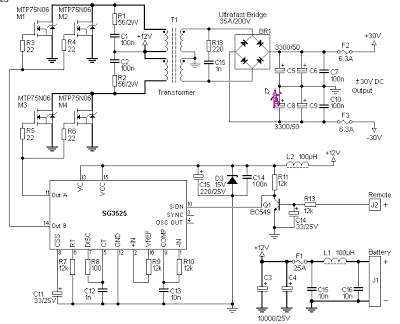
12V to 30V DC to DC Converter Schematic

 12V to +/- 30V DC to DC Converter Circuit Diagram

Converter Circuit Diagram

This is a DC to DC converter for car power amplifier. 12V input generates +30V and -30V output for preamp or power amplifiers. Circuit uses SG3525 IC, Mosfets and switching power supply. 


Wednesday, April 10, 2013

0 Comments
Posted in Arrangement, Art, Business

Step Up Converter For 20 LEDs

The circuit described here is a step-up converter to drive 20 LEDs, designed to be used as a home-made ceiling night light for a child’s bedroom. This kind of night light generally consists of a chain of Christmas tree lights with 20 bulbs each consuming 1 W, for a total power of 20 W. Here, in the interests of saving power and extending operating life, we update the idea with this simple circuit using LEDs. 

Power can be obtained from an unregulated 12 V mains adaptor, as long as it can deliver at least about 330 mA.  The circuit uses a low-cost current-mode controller type UCC3800N, reconfigured into voltage mode to create a step-up converter with simple compensation. By changing the external components the circuit can easily be modified for other applications. To use a current-mode controller as a voltage-mode controller it is necessary to couple a sawtooth ramp (rising from 0 V to 0.9 V) to the CS (current sense) pin, since this pin is also an input to the internal PWM comparator.

Circuit diagram :
Step-up Converter For 20 LEDs -Circuit-Diagram
Step-up Converter For 20 LEDs Circuit Diagram

The required ramp is present on the RC pin of the IC and is reduced to the correct voltage range by the voltage divider formed by R3 and R2. The RC network formed by R4 and C6 is dimensioned to set the switching frequency at approximately 525 kHz. The comparator compares the ramp with the divided-down version of the output voltage produced by the potential divider formed by R6 and R7. Trimmer P1 allows the output voltage to be adjusted. This enables the current through the LEDs to be set to a suitable value for the devices used. The UCC3800N starts up with an input voltage of 7.2 V and switches off again if the input voltage falls below 6.9 V. The circuit is designed so that output voltages of between 20 V and 60 V can be set using P1.

This should be adequate for most cases, since the minimum and maximum specified forward voltages for white LEDs are generally between 3 V and 4.5 V. For the two parallel chains of ten LEDs in series shown here a voltage of between 30 V and 45 V will be required. The power components D1, T1 and L1 are considerably over specified here, since the circuit was originally designed for a different application that required higher power. To adjust the circuit, the potentiometer should first be set to maximum resistance and a multimeter set to a 200 mA DC current range should be inserted in series with the output to the LEDs. Power can now be applied and P1 gradually turned until a constant current of 40mA flows. The step-up converter is now adjusted correctly and ready for use.


www.ecircuitslab.com

    Total Pageviews