Showing posts with label relay. Show all posts

Tuesday, October 1, 2013

0 Comments
Posted in Arrangement, Art, Business

Dual Relay Driver Board Circuit Schematic

A simple and convenient way to interface 2 relays for switching application in your project. This relay driver boosts the input impedance with a regular BC547 NPN transistor (or equivalent). Very common driver. It can drive a variety of relays, including a reed-relay.

Transistor Q1and Q2 are a simple common-emitter amplifier that increases the effective sensitivity of the 12 volt relay coil about a 100 times, or in other words, the current gain for this circuit is 100. Using this setup reduces the relay sensitivity to a few volts. R3 and R4 restricts the input current to Q1 and Q2 to a safe limit. Diodes D3 and D4 are EMF dampers and filter off any sparking when the relay
de-energizes.

Picture of the project:

photo_dual_relay_driver_board circuit diagram Front View Of Dual Channel Relay Board Driver

Circuit diagram:

dual_relay_driver_board_schematic_circuit_diagram

Parts:

R1-R2 = 1K
R3-R4 = 5.6K
C1-C2 = 100nF-63V
D1-D2 = Red LED
D3-D4 = 1N4001
L1-L2 = 12V Relay
Q1-Q2 = BC547

Specification:

  • Input - 12 VDC @ 84 mA
  • Output - two SPDT relay
  • Relay specification - 5 A @ 230 VAC
  • Trigger level-2~5VDC
  • Berg pins for connecting power and trigger voltage
  • LED on each channel indicates relay status

Source : www.extremecircuits.net
Wednesday, September 4, 2013

0 Comments
Posted in Arrangement, Art, Business

Single Transistor Relay Toggle

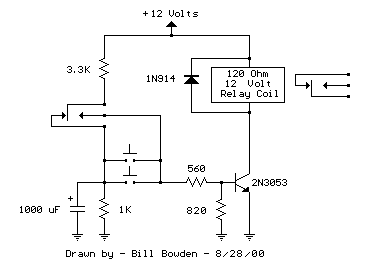
The circuit below requires a double pole, double throw relay in conjunction with a single transistor to allow toggling the relay with a momentary push button. One set of relay contacts is used to control the load, while the other is used to provide feedback to keep the relay activated or deactivated. Several push buttons can be wired in parallel to allow toggling the relay from different locations.

In the deactivated state, the relay contacts are arranged so the 1000 uF capacitor will charge to about 2.7 volts. When the switch is closed, the capacitor voltage is applied to the transistor base through a 560 resistor causing the transistor to turn on and activate the relay. In the activated state, the relay contacts are arranged so the 3.3K resistor and 560 ohm resistor provide a continous current to the transistor base maintaining the activated state. While in the activated state, the capacitor is allowed to discharge to zero through the 1K resistor. When the switch is again closed, the capacitor will cause the transistor base to move toward ground deactivating the relay.

Single Transistor Relay Toggle  Circuit Diagram


Single Transistor Relay Toggle

The circuit has three distinct advantages, it requires only a few parts, always comes up with the relay deactivated, and doesnt need any switch debouncing. However since the capacitor will begin charging as soon as the button is depressed, the button cannot remain depressed too long to avoid re-engaging the relay. This problem can be minimized with an additional resistor connected from the transistor base to ground so that the base voltage is close to 0.7 volts with the button depressed and the transistor is biased in the linear region. With the button held down, the relay coil voltage should be somewhere between the pull in and drop out voltages so that the relay will maintain the last toggled state.

This worked out to about 820 ohms for the circuit I built using a 12 volt, 120 ohm relay coil and 2N3053 transistor. Temperature changes will effect the situation but the operation is still greatly improved. I heated the transistor with a hair dryer and found that the relay will re-engage with the button held down for approximately 1 second, but this is not much of a problem under normal operation.

    Total Pageviews