Showing posts with label schematic. Show all posts

Tuesday, October 1, 2013

0 Comments
Posted in Arrangement, Art, Business

Dual Relay Driver Board Circuit Schematic

A simple and convenient way to interface 2 relays for switching application in your project. This relay driver boosts the input impedance with a regular BC547 NPN transistor (or equivalent). Very common driver. It can drive a variety of relays, including a reed-relay.

Transistor Q1and Q2 are a simple common-emitter amplifier that increases the effective sensitivity of the 12 volt relay coil about a 100 times, or in other words, the current gain for this circuit is 100. Using this setup reduces the relay sensitivity to a few volts. R3 and R4 restricts the input current to Q1 and Q2 to a safe limit. Diodes D3 and D4 are EMF dampers and filter off any sparking when the relay
de-energizes.

Picture of the project:

photo_dual_relay_driver_board circuit diagram Front View Of Dual Channel Relay Board Driver

Circuit diagram:

dual_relay_driver_board_schematic_circuit_diagram

Parts:

R1-R2 = 1K
R3-R4 = 5.6K
C1-C2 = 100nF-63V
D1-D2 = Red LED
D3-D4 = 1N4001
L1-L2 = 12V Relay
Q1-Q2 = BC547

Specification:

  • Input - 12 VDC @ 84 mA
  • Output - two SPDT relay
  • Relay specification - 5 A @ 230 VAC
  • Trigger level-2~5VDC
  • Berg pins for connecting power and trigger voltage
  • LED on each channel indicates relay status

Source : www.extremecircuits.net

Sunday, August 4, 2013

0 Comments
Posted in Arrangement, Art, Business

Gibson RD Artist Guitar circuit schematic with explanation


The following diagram is the schematic of Gibson RD Artist bass guitar

Circuit Notes:

  1. Both compression and expansion effects are determined by the lead pickup output only.
  2. I and O in the design diagram refer to inner and outer connections for the specific plug / jack.
  3. P and J in the design diagram refer to plugs and jacks respectively.
  4. The two green wires connecting to the P1- (5,6) are signal grounds. P1-8 being used for plug priority sensing.

Gibson RD Artist guitar schematic diagram designed by Fabian P Hartery

Download the schematic in PDF file:
» Download Link

Friday, July 5, 2013

0 Comments
Posted in Arrangement, Art, Business

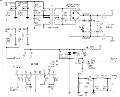
12V to 30V DC to DC Converter Schematic

 12V to +/- 30V DC to DC Converter Circuit Diagram

Converter Circuit Diagram

This is a DC to DC converter for car power amplifier. 12V input generates +30V and -30V output for preamp or power amplifiers. Circuit uses SG3525 IC, Mosfets and switching power supply. 


Wednesday, June 12, 2013

0 Comments
Posted in Arrangement, Art, Business

Low Voltage Alarm Circuit Schematic With explanation

This low voltage circuit can be used to monitor batteries and other volatile sources of current for problems. The circuit sounds an alarm and lights an LED, but can be interfaced to any number of other circuits for many different uses.Low Voltage Alarm Circuit

Parts


Part

Total Qty.

Description

Substitutions
R1, R321K 1/4W Resistor
R215K Pot
U11LM339 Op Amp IC
D111N5233B Zener Diode
D21LED
BZ11Piezo Buzzer
MISC1Board, wire, socket for IC

Notes

  1. The circuit will operate from 9V to 12V.
  2. Adjust R2 until the alarm goes off at the correct voltage.s
Source : aaroncake.net/
0 Comments
Posted in Arrangement, Art, Business

Latest Touch Alarm System circuit schematic with explanation

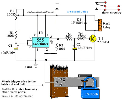
Touch Alarm circuit is widely used for security, which is installed on the door. The advantages of this alarm is because the cost is cheap and difficult to detect by burglars / intruders. The following is an example of a touch of alarm circuit which is designed by Tony Van Roon.

Touch Alarm System circuit schematic

Components List:

R1 = 100K
R2 = 56K
R3 = 10M
R4 = 220K
P1 = 100K
D1 = 1N4004
T1 = 2N3904, or equivalent
U1 = 555 Timer*
C1 = 47μF/16V**
C2 = 33μF/16V**
Re1 = Relay***

Notes:

*The 555 can be a LM, NE, or MC(cmos) type, they’re all pin-compatible.

**C1/C2′s operating voltage should be elevated to 25V if you decide to go with a 12V energy source. Rule of thumb: the operating voltage of capacitors are at least double the supplied voltage, in other words, if the powersource is 9Volt, your capacitor(s) is a minimum of 18V. Transistor T1 could be any approximate substitute.

*** Use any suitable relay for the project and if you are not tight on area, use any size. I’ve develop this specific circuit to prevent students from fiddling using the security cameras in pc labs in the University I’m employed. I made certain the metal casing was not grounded. But as the schematic shows you can essentially hook it as much as any type of metal surface. I utilized a 12-vdc power adapter. Use any appropriate relay to handle your requirements. A ‘RESET’ switch (Usually Closed) can be added between the constructive and the ‘arrow-with-the-+’. The trigger (touch) wire is connected to pin 2 of the 555 and will trigger the relay, utilizing the body resistance, when touched. It is apparent that the ‘touching’ component has to be clean and can make good get in touch with with the trigger wire. This particular circuit may not be suitable for all applications. Just in case you wonder why pin 5 isn’t listed within the schematic diagram; it isn’t truly required. In certain noisy conditions a little ceramic capacitor is placed in between pin 5 and ground. It does no harm to add one or leave it out.

Extra note: For all those of you who didn’t discover, there is an approximate 5-second delay build-in prior to activation of the relay to avoid false triggering, or a ‘would-be’ thief, etc.

Friday, May 31, 2013

0 Comments
Posted in Arrangement, Art, Business

Honda Civic Immobilizer System Circuit Diagramcircuit Schematic

Wire Diagram on 1988 Bmw 325i E30 Series Wiring Diagrams   Circuit Schematic
1988 Bmw 325i E30 Series Wiring Diagrams Circuit Schematic.


Wire Diagram on Pontiac Fiero Headrest Speakers Wiring Diagram   There Are Two Wiring
Pontiac Fiero Headrest Speakers Wiring Diagram There Are Two Wiring.


Wire Diagram on Chevrolet Tahoe   Blazer Electrical Wiring Diagram   Circuit Schematic
Chevrolet Tahoe Blazer Electrical Wiring Diagram Circuit Schematic.


Wire Diagram on Wiring Diagram Here     Free Download Pdf File   Source  Mediafire
Wiring Diagram Here Free Download Pdf File Source Mediafire.


Wire Diagram on Find More Information About 1996 Toyota Tercel Wiring Diagram And
Find More Information About 1996 Toyota Tercel Wiring Diagram And.


Wire Diagram on 1997 Chevrolet Cavalier Cruise Control System Circuit Diagram
1997 Chevrolet Cavalier Cruise Control System Circuit Diagram.


Wire Diagram on Honda Civic Immobilizer System Circuit Diagram   Circuit Schematic
Honda Civic Immobilizer System Circuit Diagram Circuit Schematic.


Wire Diagram on Wiring Harness Diagram And Electrical Troubleshooting For 2001
Wiring Harness Diagram And Electrical Troubleshooting For 2001.


Wire Diagram on Find More Information About Cadillac Deville Concours Wiring Diagram
Find More Information About Cadillac Deville Concours Wiring Diagram.


Wire Diagram on Cb100 Pictorial Diagram It Shows The Motorcycle Electrical System
Cb100 Pictorial Diagram It Shows The Motorcycle Electrical System.


Thursday, April 11, 2013

0 Comments
Posted in Arrangement, Art, Business

4 x 25 W CAR AMPLIFIER TDA7381 SCHEMATIC DIAGRAM

4 x 25 W CAR AMPLIFIER TDA7381 SCHEMATIC DIAGRAM


The TDA7381 is a class AB audio power amplifier in Flexiwatt25 package designed for car radio applications. You you can also use this circuit for other purposes. Thanks to the fully complementary PNP/NPN output configuration the TDA7381 allows a rail to rail output voltage swing with no need of bootstrap capacitors.


The extremely reduced components count allows very compact sets. The on-board clipping detector simplifies gain compression operations. The fault diagnostics makes it possible to detect mistakes during Car- Radio assembly and wiring in the car.


Absolute maximum ratings of IC TDA7295 IC


  • Operating supply voltage = 18 V
  • DC supply voltage = 28 V
  • Peak supply voltage (t = 50 ms) = 50 V
  • Output peak current Repetitive (duty cycle 10 % at f = 10 Hz) = 3 A
  • Output peak current Non repetitive (t = 100 µs) = 4A
  • Power dissipation, (Tcase = 70 °C) = 80 W
  • Junction temperature = 150 °C
  • Storage temperature = -40 to 150 °C


Monday, April 8, 2013

0 Comments
Posted in Arrangement, Art, Business

2004 2500hd Trailer Wiring Diagramcircuit Schematic

Trailer Wiring Diagram on Pin  S  Type Caravan Wiring   Uk Trailer Parts
Pin S Type Caravan Wiring Uk Trailer Parts.


Trailer Wiring Diagram on 2004 Gmc 2500hd Trailer Wiring Diagram   Circuit Schematic
2004 Gmc 2500hd Trailer Wiring Diagram Circuit Schematic.


Trailer Wiring Diagram on Electric Trailer Brake Controller Wiring
Electric Trailer Brake Controller Wiring.


Trailer Wiring Diagram on Trailer Circuit Wiring
Trailer Circuit Wiring.


Trailer Wiring Diagram on How To Install A Trailer Light Taillight Converter In Your Towing
How To Install A Trailer Light Taillight Converter In Your Towing.


Trailer Wiring Diagram on 12s Wiring Diagram
12s Wiring Diagram.


Trailer Wiring Diagram on Wiring For 13 Pin Euro Plugs   Sockets For Trailers   Caravans   Uk
Wiring For 13 Pin Euro Plugs Sockets For Trailers Caravans Uk.


Trailer Wiring Diagram on Trailer Wiring Basics For Towing
Trailer Wiring Basics For Towing.


Trailer Wiring Diagram on Way   7 Pole Rv Travel Trailer Connector Wiring Color Code
Way 7 Pole Rv Travel Trailer Connector Wiring Color Code.


Trailer Wiring Diagram on Trailer Wiring Diagrams   Etrailer Com
Trailer Wiring Diagrams Etrailer Com.


    Total Pageviews