The circuit below requires a double pole, double throw relay in conjunction with a single transistor to allow toggling the relay with a momentary push button. One set of relay contacts is used to control the load, while the other is used to provide feedback to keep the relay activated or deactivated. Several push buttons can be wired in parallel to allow toggling the relay from different locations.
In the deactivated state, the relay contacts are arranged so the 1000 uF capacitor will charge to about 2.7 volts. When the switch is closed, the capacitor voltage is applied to the transistor base through a 560 resistor causing the transistor to turn on and activate the relay. In the activated state, the relay contacts are arranged so the 3.3K resistor and 560 ohm resistor provide a continous current to the transistor base maintaining the activated state. While in the activated state, the capacitor is allowed to discharge to zero through the 1K resistor. When the switch is again closed, the capacitor will cause the transistor base to move toward ground deactivating the relay.
Single Transistor Relay Toggle Circuit Diagram
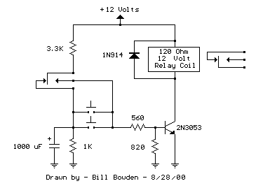
The circuit has three distinct advantages, it requires only a few parts, always comes up with the relay deactivated, and doesnt need any switch debouncing. However since the capacitor will begin charging as soon as the button is depressed, the button cannot remain depressed too long to avoid re-engaging the relay. This problem can be minimized with an additional resistor connected from the transistor base to ground so that the base voltage is close to 0.7 volts with the button depressed and the transistor is biased in the linear region. With the button held down, the relay coil voltage should be somewhere between the pull in and drop out voltages so that the relay will maintain the last toggled state.
This worked out to about 820 ohms for the circuit I built using a 12 volt, 120 ohm relay coil and 2N3053 transistor. Temperature changes will effect the situation but the operation is still greatly improved. I heated the transistor with a hair dryer and found that the relay will re-engage with the button held down for approximately 1 second, but this is not much of a problem under normal operation.
In the deactivated state, the relay contacts are arranged so the 1000 uF capacitor will charge to about 2.7 volts. When the switch is closed, the capacitor voltage is applied to the transistor base through a 560 resistor causing the transistor to turn on and activate the relay. In the activated state, the relay contacts are arranged so the 3.3K resistor and 560 ohm resistor provide a continous current to the transistor base maintaining the activated state. While in the activated state, the capacitor is allowed to discharge to zero through the 1K resistor. When the switch is again closed, the capacitor will cause the transistor base to move toward ground deactivating the relay.
Single Transistor Relay Toggle Circuit Diagram
The circuit has three distinct advantages, it requires only a few parts, always comes up with the relay deactivated, and doesnt need any switch debouncing. However since the capacitor will begin charging as soon as the button is depressed, the button cannot remain depressed too long to avoid re-engaging the relay. This problem can be minimized with an additional resistor connected from the transistor base to ground so that the base voltage is close to 0.7 volts with the button depressed and the transistor is biased in the linear region. With the button held down, the relay coil voltage should be somewhere between the pull in and drop out voltages so that the relay will maintain the last toggled state.
This worked out to about 820 ohms for the circuit I built using a 12 volt, 120 ohm relay coil and 2N3053 transistor. Temperature changes will effect the situation but the operation is still greatly improved. I heated the transistor with a hair dryer and found that the relay will re-engage with the button held down for approximately 1 second, but this is not much of a problem under normal operation.

