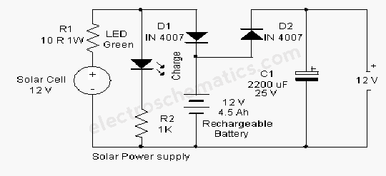
This is a simple NiCd battery charger powered by solar cells. A solar cell panel or an array of solar cells can charge a battery at more than 80 % efficiency provided the available voltage exceeds the ‘fully charged’ battery voltage by the drop across one diode, which is simply inserted between the solar cell array and the battery. Adding a step-down regulator enables a solar cell array to charge battery packs with various terminal voltages at optimum rates and with efficiencies approaching those of the regulator itself.
However, the IC must then operate in an unorthodox fashion (a.k.a. ‘Elektor mode’) regulating the flow of charge current in such a way that the solar array output voltage remains near the level required for peak power transfer. Here, the MAX639 regulates its input voltage instead of its output voltage as is more customary (but less interesting).
Circuit diagram:

The input voltage is supplied by twelve amorphous solar cells with a minimum surface area of 100 cm2. Returning to the circuit, potential divider R2/R3 disables the internal regulating loop by holding the V-FB (voltage feedback) terminal low, while divider R1/R2+R3 enables LBI (low battery input) to sense a decrease in the solar array output voltage. The resulting deviation from the solar cells’ peak output power causes LBO (low battery output) to pull SHDN (shutdown) low and consequently disable the chip. LBI then senses a rising input voltage, LBO goes high and the pulsating control maintains maximum power transfer to the NiCd cells.
Current limiting inside the MAX639 creates a ‘ceiling’ of 200 mA for I out. Up to five NiCd cells may be connected in series to the charger output. When ‘on’ the regulator chip passes current from pin 6 to pin 5 through an internal switch representing a resistance of less than 1 ohm. Benefiting from the regulator’s low quiescent current (10 microamps typical) and high efficiency (85 %), the circuit can deliver four times more power than the single-diode configuration usually found in simple solar chargers. Coil L1 is a 100-µH suppressor choke rated for 600mA.
However, the IC must then operate in an unorthodox fashion (a.k.a. ‘Elektor mode’) regulating the flow of charge current in such a way that the solar array output voltage remains near the level required for peak power transfer. Here, the MAX639 regulates its input voltage instead of its output voltage as is more customary (but less interesting).
Circuit diagram:

Solar-Powered High Efficiency Charger Circuit Diagram
The input voltage is supplied by twelve amorphous solar cells with a minimum surface area of 100 cm2. Returning to the circuit, potential divider R2/R3 disables the internal regulating loop by holding the V-FB (voltage feedback) terminal low, while divider R1/R2+R3 enables LBI (low battery input) to sense a decrease in the solar array output voltage. The resulting deviation from the solar cells’ peak output power causes LBO (low battery output) to pull SHDN (shutdown) low and consequently disable the chip. LBI then senses a rising input voltage, LBO goes high and the pulsating control maintains maximum power transfer to the NiCd cells.
Current limiting inside the MAX639 creates a ‘ceiling’ of 200 mA for I out. Up to five NiCd cells may be connected in series to the charger output. When ‘on’ the regulator chip passes current from pin 6 to pin 5 through an internal switch representing a resistance of less than 1 ohm. Benefiting from the regulator’s low quiescent current (10 microamps typical) and high efficiency (85 %), the circuit can deliver four times more power than the single-diode configuration usually found in simple solar chargers. Coil L1 is a 100-µH suppressor choke rated for 600mA.
Author: D. Prabakaran - Copyright: Elektor July-August 2004