Showing posts with label supply. Show all posts

Thursday, December 19, 2013

0 Comments
Posted in Arrangement, Art, Business

Simple Micro Power Supply Circuit Diagram

This is simple micro power supply circuit diagram. The circuit uses a CA3440 BiMOS op amp and CA3086 transistor array. The no-load current from 5-volt supply is 1.5 µ A. Load current can go as high as 200 µ and still maintain output voltage regulation within 0.05%.

 Micro Power Supply Circuit Diagram

Simple Micro Power Supply Circuit Diagram

Tuesday, September 3, 2013

0 Comments
Posted in Arrangement, Art, Business

Switching Power Supply Using the LMZ14202H

Using the LMZ14202H power switching controller, can be designed a very simple switching power supply circuit that can provide a fixed output voltage covering a wide range of voltages .

Switching Power Supply Circuit diagram


This power switching power supply electronic project will provide a fixed output voltage between 5 and 30 volt from an input voltage between 8 and 42 volt at a maximum output current of 2 ampere . This circuit project power supply require few external electronic parts and can be configured very easy . In the table bellow you can see components value that are required for different output voltage

Friday, August 9, 2013

0 Comments
Posted in Arrangement, Art, Business

High voltage Power supply Circuit Diagram

High voltage Power supply Circuit Diagram. A 6 V battery can provide 100-150 Vdc center-tapped at a high internal impedance (not dangerous though it can inflict an unpleasant jolt). A 6.3 V transformer is connected in reverse with a transistor used in a Hartley oscillator configuration. The frequency of operation may be controlled by varying the value of the 10 ohm resistor.The 10 µ¥ capacitor must have a working voltage of at least 250 Vdc .

 High voltage Power supply Circuit Diagram


High voltage Power supply Circuit Diagram

Tuesday, July 30, 2013

0 Comments
Posted in Arrangement, Art, Business

5 to 15V Regulated Power Supply Rise

Regulated Power Supply
This project is a normal DC regulated power supply that is a variable DC voltage range from 5V to 15V. It can supply current up to  400mA to power the various circuits for your electronic projects. The voltage output is varied by using the potentiometer V.R1. In this circuit, the input line power supply is designed for 240V.A.C. If 110VAC input is used, alter the ratings of the varistor to 150VAC & the transformer ratio to 110V/12V. 

Fuse F1 is used as a protection in case theres any short circuit in the circuit. Varistor V1 is connected in parallel to the input of the line voltage to clamp the surge voltage from the line to a reasonable level that helps to protect the transformer & other circuitry. One time the voltage level surge to a high level beyond the ability of the varistor to absorb it, fuse F1 or varistor V1 or both will burn. If this circuit failed after a period of operation, check that the fuse & the varistor are still in nice condition or else replace them.

Diodes D1, D2, D3 and D4 are used to rectify the 12V.A.C voltage to DC voltage. Electrolytic capacitor E1 is used as a smoothing capacitor to reduce the ripple of the DC voltage. The DC voltage is fed in to the input of 7805 regulator where the output DC voltage is obtained. Changing the worth of VR1 will alter the output of the DC voltage. Capacitor C1 is used to filter out high frequency part from the power supply.


Thursday, July 25, 2013

0 Comments
Posted in Arrangement, Art, Business

2 5A 1 25 To 25V Regulated Power Supply Circuit Diagram

This power supply uses an LM317J adjustable regulator and an MJ2955 pass transistor. Ql and U2 as well as Ul should be heats inked. A suitable heat-sink would typically be 4` 4` 1` fins, extruded type, because up to 65 W dissipation can occur. R8 and R9 should be 1% types or selected from 5% film types with an accurate ohmmeter. Capacitors are disc ceramic except for those with polarity marked, which are electrolytic. D1, D2—1-A, 100-PIV rectifier diode. DS1—Red LED. F1 —1,5-A, 3AG fuse in chassis-mount holder. J1, J2—Standard five-way binding post, one red, one black. M1—Milli-ammeter, 0-1 mA dc. Q1—NPN power transistor MJ2955 (Radio Shack) or equiv device with a + 70-V, 10-A, 150-W rating in a -204 case. R1, R2, R7—5-W wire-wound resistor. See Notes 3 and 4 for source, or, use 17 inches of no. 28 enam wire, single-layer wound, on a 10-KOhmhm, 1-W carbon-composition resistor for R1 and R7. For R2, use 36 inches of no. 30 enam wire on a 10-KOhmhm, 1-W carbon composition resistor (scramble wound). R-4—Panel-mount, 5-kfi, 2-W or 5-W potentiometer, carbon or wire wound (See Note 8). R8, R9—See text. 51—SPST toggle switch. 52—DPDT toggle or rotary wafer switch. T1—25.2-V, 2.75-A power transformer (see text). U1—6-A, 200 PIV bridge rectifier with heat sink. See text. U2—LM317T +1.25- to 30-V, 1.5-A 7-220 regulator. Use an LM317HVK (T0-204 case) for dc output voltage greater than 40. See text.

2.5A-1.25 To 25V Regulated Power Supply Circuit Diagram

2.5A-1.25 To 25V Regulated Power Supply Circuit Diagram

Wednesday, July 3, 2013

0 Comments
Posted in Arrangement, Art, Business

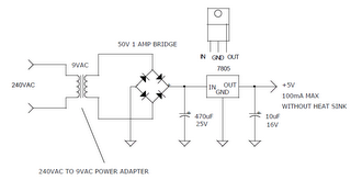
Simple 240VAC TO 5VDC POWER SUPPLY

This is simple way to power some 5v logic from a 240vac source. If a 120vac power adapter is used, the circuit will also work for 120vac power lines.
 
 
240VAC TO 5VDC POWER SUPPLY,

Sunday, April 7, 2013

0 Comments
Posted in Arrangement, Art, Business

Adapter power supply and charger circuit

Basically adapter, power supply and charger circuit has a similar construction which consists of a transformer, rectifier (rectifier) and smoothing the voltage. For there is usually an additional power supply voltage stabilizer of voltage regulator IC LM series 78XX or 79XX .
Below is a schematic circuit adapter, power supply, or battery charger (for gadgets, mobile phones, MP4player, smartphone) that is equipped with a 5V voltage stabilizer:

adapter, power supply and charger circuit
Adapter, power supply and charger circuit

    Total Pageviews