Showing posts with label system. Show all posts

Monday, October 7, 2013

0 Comments
Posted in Arrangement, Art, Business

Inexpensive Remote Watering System

This remotely controlled watering system is both inexpensive and easy to expand. It is designed to operate in conjunction with a conventional watering timer and allows remote switching between nine zones. The prototype is used in a bore system, where a deep-well pump must be started and kept running while zones are being changed. This is necessary to minimise cycling and results in maximum pump life. A standard portable telephone is used as the transmitter and receiver. The system’s range is therefore limited only by the telephone specifications. The prototype uses an Audioline model CDL1A, set to pulse-dial mode via a switch in the side. Selecting zones from the telephone keypad couldn’t be simpler.

For the first nine zones, each key number (1-9) corresponds directly to a zone number. If additional zones were added to the basic circuit, "0" would represents zone 10, while further zones are "dialed-in" by simple addition. For example, to select station 15, you’d press "0" and then "5". Looking now at the circuit, the telephone base station is wired to one input of a hex Schmitt-trigger inverter (IC5a), which functions as a low-pass filter and pulse shaper in conjunction with two 1kO resistors, a 10µF capacitor and a second inverter (IC5c). Glitch-free pulses are fed to the clock inputs of two 74HC164 8-stage shift registers (IC3 & IC4).

The A & B inputs of IC4 are permanently pulled high, so the first pulse results in a logic high at output O0 (pin 3). Each additional pulse causes the next successive output to go high. After eight pulses, output O7 (pin 13) goes high and this is propagated to the second shift register (IC4) via its A & B inputs. The shift register outputs are wired to a collection of 74HC86 exclusive-OR gates (IC6-IC8) in such a way that only one of the 74HC86 outputs can be high at a time. For example, after three clock pulses, outputs O0-O3 of IC4 are high, which results in IC7c’s output going high.

The exclusive-OR gates feed a pair of ULN2001A Darlington drivers (IC9 & IC10), which in turn drive relays to switch power to the water solenoids. If a wrong key is pressed at the remote end and 10 pulses arrive at the shift register inputs, output O1 of IC3 will go high, triggering both 555 timers (IC1 & IC2) via inverter IC5e. The 555s are configured as monostables, so their outputs immediately swing high. IC2 resets the shift registers, returning all outputs to their initial (low) state. The reset signal is held for about three seconds, which ensures that any number of additional pulses (within reason) above the maximum of nine will be ignored. In the meantime, IC1 energises one of the water solenoids via diode D2 and the zone #1 driver circuit.

This solenoid is held on for about 20 seconds, giving sufficient time for the number to be redialled after the 3-second redial "hold-off" period. This solenoid "hold-on" period is important as it prevents overheating of the pump motor that might otherwise occur without continuous water flow. The circuit operates from +5V, which is generated by a conventional bridge rectifier (BR1), filter and regulator arrangement. 24VAC for the water solenoids is obtained from the water system timer transformer and is external to this circuit.

Editor’s note:
  • For the "sorry, wrong number" feature to be effective, some form of operator feedback would be required if all of the sprinklers are not visible. Perhaps a siren could also be driven by IC1’s output to alert the operator that a valid sector number must be dialled within 20 seconds!
Wednesday, June 12, 2013

0 Comments
Posted in Arrangement, Art, Business

Latest Touch Alarm System circuit schematic with explanation

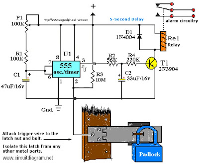
Touch Alarm circuit is widely used for security, which is installed on the door. The advantages of this alarm is because the cost is cheap and difficult to detect by burglars / intruders. The following is an example of a touch of alarm circuit which is designed by Tony Van Roon.

Touch Alarm System circuit schematic

Components List:

R1 = 100K
R2 = 56K
R3 = 10M
R4 = 220K
P1 = 100K
D1 = 1N4004
T1 = 2N3904, or equivalent
U1 = 555 Timer*
C1 = 47μF/16V**
C2 = 33μF/16V**
Re1 = Relay***

Notes:

*The 555 can be a LM, NE, or MC(cmos) type, they’re all pin-compatible.

**C1/C2′s operating voltage should be elevated to 25V if you decide to go with a 12V energy source. Rule of thumb: the operating voltage of capacitors are at least double the supplied voltage, in other words, if the powersource is 9Volt, your capacitor(s) is a minimum of 18V. Transistor T1 could be any approximate substitute.

*** Use any suitable relay for the project and if you are not tight on area, use any size. I’ve develop this specific circuit to prevent students from fiddling using the security cameras in pc labs in the University I’m employed. I made certain the metal casing was not grounded. But as the schematic shows you can essentially hook it as much as any type of metal surface. I utilized a 12-vdc power adapter. Use any appropriate relay to handle your requirements. A ‘RESET’ switch (Usually Closed) can be added between the constructive and the ‘arrow-with-the-+’. The trigger (touch) wire is connected to pin 2 of the 555 and will trigger the relay, utilizing the body resistance, when touched. It is apparent that the ‘touching’ component has to be clean and can make good get in touch with with the trigger wire. This particular circuit may not be suitable for all applications. Just in case you wonder why pin 5 isn’t listed within the schematic diagram; it isn’t truly required. In certain noisy conditions a little ceramic capacitor is placed in between pin 5 and ground. It does no harm to add one or leave it out.

Extra note: For all those of you who didn’t discover, there is an approximate 5-second delay build-in prior to activation of the relay to avoid false triggering, or a ‘would-be’ thief, etc.

Friday, May 31, 2013

0 Comments
Posted in Arrangement, Art, Business

Honda Civic Immobilizer System Circuit Diagramcircuit Schematic

Wire Diagram on 1988 Bmw 325i E30 Series Wiring Diagrams   Circuit Schematic
1988 Bmw 325i E30 Series Wiring Diagrams Circuit Schematic.


Wire Diagram on Pontiac Fiero Headrest Speakers Wiring Diagram   There Are Two Wiring
Pontiac Fiero Headrest Speakers Wiring Diagram There Are Two Wiring.


Wire Diagram on Chevrolet Tahoe   Blazer Electrical Wiring Diagram   Circuit Schematic
Chevrolet Tahoe Blazer Electrical Wiring Diagram Circuit Schematic.


Wire Diagram on Wiring Diagram Here     Free Download Pdf File   Source  Mediafire
Wiring Diagram Here Free Download Pdf File Source Mediafire.


Wire Diagram on Find More Information About 1996 Toyota Tercel Wiring Diagram And
Find More Information About 1996 Toyota Tercel Wiring Diagram And.


Wire Diagram on 1997 Chevrolet Cavalier Cruise Control System Circuit Diagram
1997 Chevrolet Cavalier Cruise Control System Circuit Diagram.


Wire Diagram on Honda Civic Immobilizer System Circuit Diagram   Circuit Schematic
Honda Civic Immobilizer System Circuit Diagram Circuit Schematic.


Wire Diagram on Wiring Harness Diagram And Electrical Troubleshooting For 2001
Wiring Harness Diagram And Electrical Troubleshooting For 2001.


Wire Diagram on Find More Information About Cadillac Deville Concours Wiring Diagram
Find More Information About Cadillac Deville Concours Wiring Diagram.


Wire Diagram on Cb100 Pictorial Diagram It Shows The Motorcycle Electrical System
Cb100 Pictorial Diagram It Shows The Motorcycle Electrical System.


Friday, April 5, 2013

0 Comments
Posted in Arrangement, Art, Business

SWR Meter

At transmission channel that is not match besides incident wave flows also reflected wave. The direction is incident wave from source of to burden (from transmitter to antenna), while reflected wave from direction that is on the contrary (from antenna towards to transmitter). To measure the wave power is required by Power Meter. Usually at Power Meter there are two scales, firstly applied for power to come and other for reflects power. Level of scale is for reflect power smaller than coming power scale.

SWR METER (Standing Wave Ratio Meter - standing wave comparison meter) applied to measure comparison of incident wave and reflected wave. Equally SWR METER applied to measure how to match a source with burden. Job (activity principle SWR Meter constituted at Power Meter. if at one particular measurement only there is Power Meter hence countable SWR from power comes and reflects power.

0 Comments
Posted in Arrangement, Art, Business

5 3W Amplifier With Surround System

The AN7147 Dual 5.3-watt Audio Power Amplifier from Panasonic is listed as a ‘replacement type’ so hopefully will be around for some time to come. Together with some extra components, it can represent a simple surround-sound system requiring no opamps or a negative voltage supply. As shown by the circuit diagram the basic stereo amplifier is changed into a surround-sound system by a trick called ‘adding feedback from the opposite channel’. When surround sound is required, the negative feedback signals supplied by C13-R3 and C12-R4 are fed to the inputs of the ‘other’ amplifier. The resulting phase difference causes the surround effect. If surround sound is not required, the effect can be disabled by pressing push-button S1.

Circuit diagram :

Simple_Surround_Amplifier_Circuit_Diagram5.3W Amplifier With Surround System Circuit Diagram

This causes the bistable built around IC2.A and IC2.B to toggle and drive transistors T1 and T2 such that the above mentioned negative feedback signals are effectively shunted to ground. A high-efficiency LED and a 3.3-kΩ series resistor (R14) should be used to make sure the maximum output current of the CMOS 4001 device is not exceeded. The amplifier should not be loaded with impedances smaller than 3Ω. The AN7147 will typically supply up to 4.3 watts into 4 Ω. The SIL-12 case needs to be cooled wit a small heatsink of about 6 K/W or better. The quiescent current is modest at just 19 mA.

Source : www.extremecircuits.net

    Total Pageviews