Showing posts with label with. Show all posts

Friday, January 10, 2014

0 Comments
Posted in Arrangement, Art, Business

Digital Counter with an Interval of Kilometers

The circuit has been designed for a person who loves to jog or walk while measuring the distance that have been covered during the activity.

  • 4093 – a quad 2-input NAND with Schmitt trigger inputs integrated circuit, generally characterized by small fluctuation in voltage supply, very high impedance, outputs that can sink and source, one output can drive up to 50 inputs, high speed gate propagation time, high frequency, and low power consumption.
  • 4026 – a decade counter where the count advances as the clock input becomes high and has a maximum current of about 1 mA with a 4.5 V supply and 4 mA with a 9 V supply, which can light the appropriate segments of a common cathode 7-segment display.
  • 4024 – a ripple counter with glitches that may occur in any logic state systems connected to its outputs due to the slight delay before the later counter outputs respond to a clock pulse; the count advances as the clock input becomes low on the falling edge as indicated by the bar over the clock label that is the usual behavior of the ripple counters which means a counter output can directly drive the clock input of the next counter in a chain.

The whole circuit may be placed in a small box and be placed in pants’ pocket where the 7-segment digital display shows the most significant digit D2 in the leftmost portion where it shows the 0 to 9 Km digits. The dot in between is always ON to segregate KM form hm. The least significant digit D1 is displayed at the rightmost part where it illustrates hundreds of meters and the dot is illuminating after every 50 meters of walking. In every two steps, a beeper will signal each count of unit, although it is not included in this circuit.

Circuit diagram :

digital-counter-with-an-interval-of-kilomete Circuit

Digital Counter with an Interval of Kilometers Circuit Diagram

A length of 78 centimeters is the calculated measure of a normal step which causes the LED to illuminate after 64 steps to signal a 50 meter distance. For a mercury switch, the illumination occurs every 32 steps. After 128 steps, the display will indicate 100 meters and so on. The SPST push button switch P2 is pressed only upon request in case of low battery consumption. Both push button switches P1 & P2 should be pressed together to reset the circuit in order to prevent accidental reset of the counters. The circuit should be considered as an approximation and not as a precision meter because it is very difficult to obtain the correct position of the mercury switch SW1 in the box where the degree of slope is being set.

The excessive bouncing of mercury switch is provided with certain degree of tolerance from the monostable multivibrator consisting of IC1A & IC1B. IC2 therefore is divided by 64 as a clean square pulse enters. The LED dot segment of D1 is driven by Q2 for every 32 pulses counted by IC2. At each monostable count, an audio frequency square is generated by IC1C for a short time. Using SW2 will disable the beep while the piezo sounder is driven by Q1. The power of beeper sound can be adjusted by trimming the value of R6. SW3 can be omitted when the display is disabled resulting to negligible current consumption.

The digital step counter circuit is widely used by people as their motion monitor while walking or jogging and other most ideal exercise possible. Some designs may come with a digital clock and backlight for easy reading during running, and belt clips.

Sunday, December 22, 2013

0 Comments
Posted in Arrangement, Art, Business

Mini Box 2W Amplifier with Bass Boost Switch

This amplifier was designed to be self-contained in a small loudspeaker box. It can be feed by Walkman, Mini-Disc, iPod and CD players, computers and similar devices fitted with line or headphone output. Of course, in most cases you will have to make two boxes to obtain stereo.
Mini-Box 2W Amplifier Circuit Diagram
The circuit was deliberately designed using no ICs and in a rather old-fashioned manner in order to obtain good harmonic distortion behavior and to avoid hard to find components. The amplifier(s) can be conveniently supplied by a 12V wall plug-in adapter. Closing SW1 a bass-boost is provided but, at the same time, volume control must be increased to compensate for power loss at higher frequencies.

In use, R9 should be carefully adjusted to provide minimal audible signal cross-over distortion consistent with minimal measured quiescent current consumption; a good compromise is to set the quiescent current at about 10-15 mA. To measure this current, wire a DC current meter temporarily in series with the collector of Q3.

Parts:


P1_____________10K Log.Potentiometer
R1,R2__________33K 1/4W Resistors
R3_____________33R 1/4W Resistor
R4_____________15K 1/4W Resistor
R5,R6___________1K 1/4W Resistors
R7____________680R 1/4W Resistor
R8____________120R 1/2W Resistor
R9____________100R 1/2W Trimmer Cermet
C1,C2__________10µF 63V Electrolytic Capacitors
C3____________100µF 25V Electrolytic Capacitor
C4,C7_________470µF 25V Electrolytic Capacitors
C5_____________47pF 63V Ceramic Capacitor
C6____________220nF 63V Polyester Capacitor
C8___________1000µF 25V Electrolytic Capacitor
D1___________1N4148 75V 150mA Diode
Q1____________BC560C 45V 100mA PNP Low noise High gain Transistor
Q2____________BC337 45V 800mA NPN Transistor
Q3____________TIP31A 60V 4A NPN Transistor
Q4 ___________TIP32A 60V 4A PNP Transistor
SW1___________SPST switch
SPKR__________3-5 Watt Loudspeaker, 8, 4 or 2 Ohm impedance

Sunday, September 22, 2013

0 Comments
Posted in Arrangement, Art, Business

Alarm Clock With Day Selector

This  circuit disables an alarm clock on Saturdays and Sundays when people like to sleep in but enables normal operation on Mondays to Fridays so that people rise in time for work or school. The core of the circuit is a 4017 decade counter which acts as the day counter and it is used in conjunction with a desk clock which acts the alarm and a watch module with alarm function which provides one clock pulse very day to the 4017. In operation, the watch module feeds a day pulse via transistor Q3 to the clock input of IC1. This has seven outputs connected via day switches (S1-S7) and diodes D3-D9 to Q1 which disables the alarm signal to the speaker via transistor Q2. LEDs1-7 indicate the actual day (if you forget!).

Circuit diagram:

Alarm-clock-with-day Selector Circuit Diagram

Alarm Clock With Day Selector Circuit Diagram

To set the system, set the desk clock for the correct time and for the desired alarm time (eg, 6’o’clock). The watch module is set to the correct time and its alarm set to midnight. The day counter, IC1, is set to the correct day, as indicated by the LEDs, by pushing switch S12 and closing switch S8 or S9. S8 is normally left open to conserve the battery by leaving the LEDs off. As shown on the circuit, switches S1-S7 are set to sound the alarm on Mondays to Fridays and disable it on Saturday and Sunday. However, you can change the days to suit your work habits.

Author: Rasim Kucalovic - Copyright: Silicon Chip Electronics

Thursday, August 8, 2013

0 Comments
Posted in Arrangement, Art, Business

12 V battery charger with PUT

A
short-circuit proof battery charger will provide an average charging
current of about 8A to a 12V lead-acid storage battery. The Charger
circuit has an additional advantage, it will not function nor will it be
damaged by improperly connecting the battery to the circuit. With 220V
at the input , the circuit comences to function when the battery is
properly attached.

simple battery charger
The
battery provides the current to charge the timing capacitor C1 used in
the PUT relaxation oscillator.When C1 charges to the peak point
voltage the PUT , the PUT fires turning the SCR on , which in turn
applies charging current to the battery. As the battery charges , the
battery voltage increases slightly which increases the peak point
voltage of the PUT. The voltage on C1 increases until the zener voltage
of D1 is reached , which clamps the voltage on C1 , and thus prevents
the PUT oscillator from oscillating and charging ceases. The maximum
battery voltage is set by potentiometer R2 which sets the peak point
firing voltage pf the PUT . In the circuit shown , the charging voltage
can be set from 10 V to 14 V - the Lower limit being set by D1 and the
upper limit by T1.


Part List :

Resistor
R1 = 10K
R2 = 50K trim
R3 = 47K
R4 = 1K

Capacitor
C1 = 0.1uF

Diode , SCR , PUT
B1 = MDA990-1
D1 = 1N5240 10V
SCR = 2N5164
PUT = MPU131

Transformer , Inductor
T1 = Stepdown 220V to 14V
T2 = 11Z12 1:1 

Sunday, August 4, 2013

0 Comments
Posted in Arrangement, Art, Business

Gibson RD Artist Guitar circuit schematic with explanation


The following diagram is the schematic of Gibson RD Artist bass guitar

Circuit Notes:

  1. Both compression and expansion effects are determined by the lead pickup output only.
  2. I and O in the design diagram refer to inner and outer connections for the specific plug / jack.
  3. P and J in the design diagram refer to plugs and jacks respectively.
  4. The two green wires connecting to the P1- (5,6) are signal grounds. P1-8 being used for plug priority sensing.

Gibson RD Artist guitar schematic diagram designed by Fabian P Hartery

Download the schematic in PDF file:
» Download Link

Saturday, July 6, 2013

0 Comments
Posted in Arrangement, Art, Business

Laptops Cord Stays off Your Lap with this Clip

Someone just got this trick works on all the uni body Mac Books and helps keep your wires and cord under control.

Hacks and Mods: Laptops Cord Stays off your Lap with this Clip

This clip is especially bendy if you are lounging on the sofa with the power-cord-side in towards the cushions. It keeps your MacBooks power cord under control with this trick and to stop it from tugging in you. Its built-in cable clip the one that keeps your cord wrapped around the power brick and clip it to the side of your laptops screen.
Hacks and Mods:   Laptops Cord Stays off your Lap with this Clip
The cable pulls it up off your lap and keeps it neat and tidy not to mention free of crazy fall across the keyboard loops.


Source by : Streampowers

Wednesday, June 12, 2013

0 Comments
Posted in Arrangement, Art, Business

Low Voltage Alarm Circuit Schematic With explanation

This low voltage circuit can be used to monitor batteries and other volatile sources of current for problems. The circuit sounds an alarm and lights an LED, but can be interfaced to any number of other circuits for many different uses.Low Voltage Alarm Circuit

Parts


Part

Total Qty.

Description

Substitutions
R1, R321K 1/4W Resistor
R215K Pot
U11LM339 Op Amp IC
D111N5233B Zener Diode
D21LED
BZ11Piezo Buzzer
MISC1Board, wire, socket for IC

Notes

  1. The circuit will operate from 9V to 12V.
  2. Adjust R2 until the alarm goes off at the correct voltage.s
Source : aaroncake.net/
0 Comments
Posted in Arrangement, Art, Business

7 Segment LED Counter Circuit With explanation

This simple counter can be used to count pulses, as the basis for a customer counter (like you see at the doors of some stores), or for anything else that may be counted. The circuit accepts any TTL compatible logic signal, and can be expanded easily (see Notes). 7 Segment LED Counter Circuit With explanation

Parts

Part
Total Qty.
Description
Substitutions
R1-R77470 Ohm 1/4 Watt Resistor
U1174LS90 TTL BCD Counter IC7490,74HC90
U2174LS47 TTL Seven Segment Display Driver IC7447,74HC47
DISP11Common Anode 7 Segment LED Display
MISC1Board, Sockets For ICs, Wire


Notes

  1. All pulses to be counted are to be TTL compatible. They should not exeed 5V and not fall below ground.
  2. You can add more digits by building a second (or third, or fourth, etc...) circuit and connecting the pin 11-6 junction of the 74LS90 and 74LS47 to pin 14 of the 74LS90 in the other circuit. You can keep expanding this way to as many digits as you want.
www.aaroncake.net
0 Comments
Posted in Arrangement, Art, Business

Latest Touch Alarm System circuit schematic with explanation

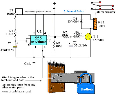
Touch Alarm circuit is widely used for security, which is installed on the door. The advantages of this alarm is because the cost is cheap and difficult to detect by burglars / intruders. The following is an example of a touch of alarm circuit which is designed by Tony Van Roon.

Touch Alarm System circuit schematic

Components List:

R1 = 100K
R2 = 56K
R3 = 10M
R4 = 220K
P1 = 100K
D1 = 1N4004
T1 = 2N3904, or equivalent
U1 = 555 Timer*
C1 = 47μF/16V**
C2 = 33μF/16V**
Re1 = Relay***

Notes:

*The 555 can be a LM, NE, or MC(cmos) type, they’re all pin-compatible.

**C1/C2′s operating voltage should be elevated to 25V if you decide to go with a 12V energy source. Rule of thumb: the operating voltage of capacitors are at least double the supplied voltage, in other words, if the powersource is 9Volt, your capacitor(s) is a minimum of 18V. Transistor T1 could be any approximate substitute.

*** Use any suitable relay for the project and if you are not tight on area, use any size. I’ve develop this specific circuit to prevent students from fiddling using the security cameras in pc labs in the University I’m employed. I made certain the metal casing was not grounded. But as the schematic shows you can essentially hook it as much as any type of metal surface. I utilized a 12-vdc power adapter. Use any appropriate relay to handle your requirements. A ‘RESET’ switch (Usually Closed) can be added between the constructive and the ‘arrow-with-the-+’. The trigger (touch) wire is connected to pin 2 of the 555 and will trigger the relay, utilizing the body resistance, when touched. It is apparent that the ‘touching’ component has to be clean and can make good get in touch with with the trigger wire. This particular circuit may not be suitable for all applications. Just in case you wonder why pin 5 isn’t listed within the schematic diagram; it isn’t truly required. In certain noisy conditions a little ceramic capacitor is placed in between pin 5 and ground. It does no harm to add one or leave it out.

Extra note: For all those of you who didn’t discover, there is an approximate 5-second delay build-in prior to activation of the relay to avoid false triggering, or a ‘would-be’ thief, etc.

0 Comments
Posted in Arrangement, Art, Business

Safely Driving With Dual LCD Display Digital Alcohol Breath Tester

If you had a digital alcohol breath tester on hand after you had a few drinks you could have easily and conveniently measured your blood alcohol content to be certain it was safe and legal for you to get behind the wheel. You are really taking a gamble on those occasions when you think youre okay to drive but yoere not certain if youre under the legal blood alcohol content. Here I will show the dual lcd display digital alcohol breath tester with audible alert white.


There is no doubted that this alcohol breath tester is compact enough for you to carry in your pocket all the time. About 13,000 people a year are killed on our roads in drink-drive incidents, so we must continue to be vigilant in our efforts to prevent drunk driving. Breath analysis is the most common method of testing for blood-alcohol content in use today, it can ensure the safety of yourself and others! Nobody wants a DUI conviction or its consequences - you risk a night in jail, thousands of dollars in fines and legal fees, the embarassing publication after a trial. You had better not drive if you are not sure, just play it safe and call a cab - the cheapest alternative.

Features

* Backlight LCD display
* Replaceable sensor module
* Dual LCD screen breathalyzer
* Quick response and resume
* Auto power off
* Temperature display in ℃ or °F
* Digital alcohol Breath Tester with audible alert
* Professional airway design, LCD screen display
* Accumulative test record counting display before tests
* Promptly and conveniently design alcohol breath analyser for measuring BAC
* A simple method to analyse blood alcohol concentration at anytime and anywhere
* Countdown & count-up timer keep the time limit of your parking
* LCD Alcohol Tester Breathalyzer uses 2 x AAA alkaline batteries(batteries not included), clock use 1 x * AG13 button cell (batteries not included)
* This Alcohol Breath Tester with LCD screen and noncontact expiring design is compact and lightweight
* This Digital Alcohol Detector is pretty easy for carrying and convenient for using
* Numbers will be shown on the LCD screen so that you can judge by analyzing the numbers
* And if the alcohol content of tested expiring gas is out of range, this LCD Alcohol Tester Breathalyzer will automatically gives out audible alert
* This personal LCD Alcohol Tester Breathalyzer measures your blood alcohol level via a breath test anytime you need to know if youve crossed the line between safe and not safe
* Pretty useful as it is, such an LCD Alcohol Tester Breathalyzer is a really a good gift for yourself or anyone else you cares
* Lightweight and easy to use, this mini breathalyzer uses illuminating lights to tell you the outcome of your breath test
* Advanced semiconductor sensor with high accuracy and repeatability

Sunday, May 19, 2013

0 Comments
Posted in Arrangement, Art, Business

Nonlinear Load Problems with Stand by Generators

If a facility’s electrical loads, such as computer power supplies, variable speed drives, electronic lighting ballasts, or other similar nonlinear electrical equipment, is furnished with switch-mode power supplies, it is imperative that you advise the generator supplier of this situation so that proper steps can be taken to avoid equipment overheating or other problems due to harmonics. Some generator manu- facturers recommend low-impedance generators and have developed winding design techniques to reduce the effects of the harmonic currents generated. The key issue is maintaining the ability to produce a stable voltage waveform and a stable frequency.

This is mostly an issue of voltage regulation system design, but can also be impacted by the governing (fuel control) system design. The winding arrangement is not as critical as the impedance of the machine relative to the utility service. The closer it is to what the utility provides, the more like the utility it will operate and the lower probability of problems. In some instances, the generator may have to be de-rated and the neutral size increased to safely supply power to nonlinear loads. When a standby generator and UPS are integrated in a system together, problems occur that typically do not exist with a UPS system or generator when they are operating alone in a system. Problems arise only when the UPS and standby generator are required to function together. Neither the UPS nor the standby generator manufacturer is at fault, and both manufacturers would probably need to work together to solve the problem. The following are common problems and solutions when applying a design that incorporates a standby generator and UPS.

1. Line Notches and Harmonic Current. The UPS manufacturer using a properly designed passive filter can address the problem of both line notches and harmonic currents. Most generator manufacturers have de-rating information to solve harmonic heating problems. However, an input filter on the UPS that reduces the harmonics to less than 10% at full load eliminates the need for de-rating the generator.

2. Step Loading. When a generator turns on and the ATS switch connecting it to the UPS closes, the instantaneous application of the load to the generator will cause sudden swings in both voltage and frequency. This condition can generally be evaded by verifying that the UPS has a walk-in feature. This requires that the UPS rectifier have some means of controlling power flow so that the power draw of the UPS can slowly be applied to the generator between a 10- and 20-second timeframe.

3. Voltage Rise. This is an application problem that transpires when a generator is closely designed and sized to the UPS and there is little or no other electrical load  on the generator. When the UPS is first connected to the generator by the ATS, its charger has turned off so that it may begin its power “walk-in” routine. If the input filter is the only load on the generator, it may provide increased excitation energy for the generator. The issue is the capability of the alternator to absorb the reactive power generated by the filters. The amount that can be absorbed varies considerably between different machines from the same manufacturer. System designers should evaluate the capability in the initial design of the system to avoid problems. The outcome is that the voltage roams up without control to approximately 120% by some fundamental generator design constraint, typically magnetic saturation of the generator iron. If the value does hit 120% of the nominal, it will be damaging or disruptive to the system operation. However, a UPS that disconnects its filter when its charger is off avoids this predicament altogether.

4. Frequency Fluctuation. Generators possess inherent limitations on how closely they can manage frequency regarding their response to changing electrical loads. The function is complicated and not only involves generator features, such as rotational inertia and governor speed response, but also involves the electrical load’s reaction to frequency changes. The UPS charger, conversely, also has inherent limitations on how closely it can control its power needs from a source with fluctuations in voltage and frequency. Since both the generator controls and the UPS charger controls are affected by and respond to the frequency, an otherwise small frequency fluctuation may be exasperated. The most noticeable effect of this fluctuation is a recurring alarm that is found on the bypass of the UPS, announcing that the generator frequency is changing faster than a UPS inverter can follow. In order to minimize or eliminate frequency fluctuation problems, good control design from both the engine generator and UPS manufacturer are required. The engine must have a responsive governor, appropriately sized and adjusted for the system. The UPS manufacturer should have a control responsive to fast frequency fluctuations.

5. Synchronizing to Bypass. Some applications require the UPS to synchronize to bypass so that the critical load may be transferred to the generator. This generally places tighter demands on the generator for frequency and voltage stability. When this is the case, the system integration problem may be intensified. As described above, good control design can usually reverse this problem.

6. Automatic Transfer Switch. Most generator/UPS projects incorporate automatic transfer switches that switch the UPS back to utility power once it becomes available again. The speed of transfer can be an obstacle and may result in a failed transfer. This in turn will lead to nuisance tripping of circuit breakers or damage to loads. If the ATS switch also has motor loads, such as HVAC systems, the UPS input filter will supply excitation energy during the transfer. This excitation source turns these motors into generators using their inertia as an energy source and also their alternator field strength. If the transfer occurs too fast, causing an unexpected phase change in the voltage, the consequences can be devastating for both the motors and the UPS. One of the best solutions is to simply slow the transfer switch operation speed so that the damaging condition does not exist. Rather than switching from source to source in one-tenth of a second, slowing to one-half of a second will resolve the problem. UPS manufacturers can resolve this problem by providing a fast means of detecting the transfer and disconnecting the filter.

Tuesday, April 9, 2013

0 Comments
Posted in Arrangement, Art, Business

10W AUDIO AMPLIFIER WITH BASS BOOST ELECTRONIC DIAGRAM

10W AUDIO AMPLIFIER WITH BASS-BOOST ELECTRONIC DIAGRAM

Adjust the volume control on the minimum and R3 position with a minimum value of resistance as well. try to switch the circuit set in R3 to read the flow of about 20 to 25mA. Wait for 15 minutes, connect the ground of A1, P1, C2, C3dan C4. Connect the output also C9 ground

List Component

  • P1 : 22K Log Potemsiometer (Dual gang for stereo)
  • C3, 4 : 470uF/25V
  • P2 : 100K Log Potemsiometer (Dual gang for stereo)
  • C6 : 47pF 63V ceramic ar polyester capasitor
  • R2, 4, 8 : 820R 1/4W
  • C7 : 10nF 63V polyester capasitor
  • R1 : 4K7 1/4W
  • C9 : 100nF 63V polyester capasitor
  • R3 : 500R 1/2W
  • D1 : 1N4148 75V 150mA Diode
  • R5 : 82K 1/4W
  • IC 1 : NE5532 Low noise Dual Op-amp
  • R6, 7 : 47K 1/4W
  • Q1 : BC547B 45V 100mA NPN Transitor
  • R9 : 10R 1/2W
  • Q2 : BC557B 45V 100mA PNP Transitor
  • R10 : 0,22 4W(wirewound)
  • Q3 : TIP42A 60V 6A PNP Transistor
  • C1, 8 : 470nF 63V polyester capasitor
  • Q4 : TIP41A 60V 6A NPN Transistor
  • C2, 5 : 100uF/25V J1 : RCA audio input socket

Friday, April 5, 2013

0 Comments
Posted in Arrangement, Art, Business

5 3W Amplifier With Surround System

The AN7147 Dual 5.3-watt Audio Power Amplifier from Panasonic is listed as a ‘replacement type’ so hopefully will be around for some time to come. Together with some extra components, it can represent a simple surround-sound system requiring no opamps or a negative voltage supply. As shown by the circuit diagram the basic stereo amplifier is changed into a surround-sound system by a trick called ‘adding feedback from the opposite channel’. When surround sound is required, the negative feedback signals supplied by C13-R3 and C12-R4 are fed to the inputs of the ‘other’ amplifier. The resulting phase difference causes the surround effect. If surround sound is not required, the effect can be disabled by pressing push-button S1.

Circuit diagram :

Simple_Surround_Amplifier_Circuit_Diagram5.3W Amplifier With Surround System Circuit Diagram

This causes the bistable built around IC2.A and IC2.B to toggle and drive transistors T1 and T2 such that the above mentioned negative feedback signals are effectively shunted to ground. A high-efficiency LED and a 3.3-kΩ series resistor (R14) should be used to make sure the maximum output current of the CMOS 4001 device is not exceeded. The amplifier should not be loaded with impedances smaller than 3Ω. The AN7147 will typically supply up to 4.3 watts into 4 Ω. The SIL-12 case needs to be cooled wit a small heatsink of about 6 K/W or better. The quiescent current is modest at just 19 mA.

Source : www.extremecircuits.net

    Total Pageviews