Wednesday, September 11, 2013

0 Comments
Posted in Arrangement, Art, Business

Sensitized Solar Cells Based on Zinc Compounds

Researchers at the University of Basel in Switzerland say they have developed a new approach to producing environmentally sustainable photovoltaic devices. The research team developed a new method for producing dye substances and attaching them to the surface of titanium dioxide nanoparticles. With this they demonstrated that simple dye compounds based on zinc, a readily available metal, can be used.


Dye-Sensitized Solar Cells Based on Zinc Compounds
 
Dye-sensitized solar cells (DSCs) consist of titanium dioxide, a semiconductor material coated with a colored dye. The dye absorbs sunlight and injects electrons into the titanium dioxide, which ultimately results in a photovoltaic current. Conventional DSCs use ruthenium dyes, but ruthenium is very rare and expensive. The research team showed that dyes made with abundant and relatively inexpensive copper are effective in DSCs, and that low-cost zinc compounds can also be used. Although the new devices are not yet especially efficient, the finding opens the way to new generations of DSCs with previously ignored dye types.

Tuesday, September 10, 2013

0 Comments
Posted in Arrangement, Art, Business

12V DC to 220V 100W Inverter Circuit Diagram

12V DC to 220V 100W Inverter Circuit Diagram
12V DC to 220V 100W Inverter

This is 100W inverter circuit. It uses 4047 IC and IRF540 Mosfet instead of 2N3055 transistor. Power output is 100W from 2-3A transformer.
0 Comments
Posted in Arrangement, Art, Business

Build a Doorbell Circuit For Deaf People

This circuit provides a delayed visual indication when a door bell switch is pressed. In addition, a DPDT switch can be moved from within the house which will light a lamp in the door bell switch. The lamp can illuminate the words "Please Wait" for anyone with walking difficulties.

 Doorbell Circuit Diagram

 Doorbell Circuit Diagram


Notes:
The circuit uses standard 2 wire doorbell cable or loudspeaker wire. In parallel with the doorbell switch, S1, is a 1N4001 diode and a 12 volt 60mA bulb.

The bulb is optional, it may be useful for anyone who is slow to answer the door, all you need to do is flick a switch inside the house, and the bulb will illuminate a label saying Please Wait inside the doorbell switch or close to it.

The double pole double throw switch sends the doorbell supply to the lamp, the 22 ohm resistor is there to reduce current flow, should the doorbell switch, S1 be pressed while the lamp is on.

The resistor needs to be rated 10 watts, the 0.5 Amp fuse protects against short circuits.

When S2 is in the up position (shown as brown contacts), this will illuminate the remote doorbell lamp. When down, (blue contacts) this is the normal position and will illuminate the lamp inside the house. Switch S1 will then charge the 47u capacitor and operate the transistor which lights the lamp.

As a door bell switch is only pressed momentarily, then the charge on the capacitor decays slowly, resulting in the lamp being left on for several seconds. If a longer period is needed then the capacitor may be increased in value.

Wednesday, September 4, 2013

0 Comments
Posted in Arrangement, Art, Business

Single Transistor Relay Toggle

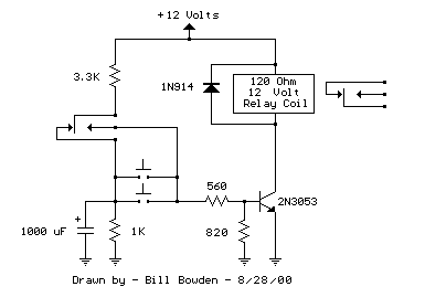
The circuit below requires a double pole, double throw relay in conjunction with a single transistor to allow toggling the relay with a momentary push button. One set of relay contacts is used to control the load, while the other is used to provide feedback to keep the relay activated or deactivated. Several push buttons can be wired in parallel to allow toggling the relay from different locations.

In the deactivated state, the relay contacts are arranged so the 1000 uF capacitor will charge to about 2.7 volts. When the switch is closed, the capacitor voltage is applied to the transistor base through a 560 resistor causing the transistor to turn on and activate the relay. In the activated state, the relay contacts are arranged so the 3.3K resistor and 560 ohm resistor provide a continous current to the transistor base maintaining the activated state. While in the activated state, the capacitor is allowed to discharge to zero through the 1K resistor. When the switch is again closed, the capacitor will cause the transistor base to move toward ground deactivating the relay.

Single Transistor Relay Toggle  Circuit Diagram


Single Transistor Relay Toggle

The circuit has three distinct advantages, it requires only a few parts, always comes up with the relay deactivated, and doesnt need any switch debouncing. However since the capacitor will begin charging as soon as the button is depressed, the button cannot remain depressed too long to avoid re-engaging the relay. This problem can be minimized with an additional resistor connected from the transistor base to ground so that the base voltage is close to 0.7 volts with the button depressed and the transistor is biased in the linear region. With the button held down, the relay coil voltage should be somewhere between the pull in and drop out voltages so that the relay will maintain the last toggled state.

This worked out to about 820 ohms for the circuit I built using a 12 volt, 120 ohm relay coil and 2N3053 transistor. Temperature changes will effect the situation but the operation is still greatly improved. I heated the transistor with a hair dryer and found that the relay will re-engage with the button held down for approximately 1 second, but this is not much of a problem under normal operation.

    Total Pageviews