Showing posts with label simple. Show all posts

Friday, January 10, 2014

0 Comments
Posted in Arrangement, Art, Business

Simple Optical Theremin Circuit Diagram

Normally, Theremin works by detecting hand proximity using capacitive coupling method. A Theremin circuit shown in the schematic diagram below use different method to control the pitch. The oscillator of this tone generator, both the volume and frequency  are controlled using LDRs, a light sensitive electronic component, so we can call this circuit an optical Theremin.  Look at the following schematic diagram.

 Simple Optical Theremin Circuit Diagram

 Simple Optical Theremin Circuit Diagram


LDR1 control the frequency of this Theremin, while LDR2 control the volume level. We can place the LDR in two boxes where we can use our hand to control the aperture of the box, allowing smooth control of light amount that expose the LDR. 

This light is expected to come from ambient light, entering the box through the hand controlled aperture. This optical Theremin assume a stable ambient light to produce smooth control. The output will be heard on a small loudspeaker, but will be in very low volume. You can just amplify this output with a standard audio power amplifier to get better loudness.

Thursday, January 9, 2014

0 Comments
Posted in Arrangement, Art, Business

Simple 4 Channel Video Amplifier using NJM2582

A very simple 4 channel video amplifier electronic circuit project can be designed using NJM2582 ic suitable for video applications with SCART connector . Design of the circuit is very simple and require few external electronic parts .

Circuit diagram :

4 channel-video-amplifier Circuit Daigram

Simple 4 Channel Video Amplifier Circuit Diagram

Some features of the NJM2582 are : Operating Voltage ±5V, +5V, +11V ; 6input 4output , 2input 1output Video SW , Internal LPF , 6dB Amplifier , Internal 75Ω Driver Circuit , DC output for SCART (FUNCTION SW, BLANKING) .

Thursday, December 26, 2013

0 Comments
Posted in Arrangement, Art, Business

Simple Strip LED Lamp

Strip LEDs are available in different colours powered by direct current (DC) source. These LEDs  are available as surface mount devices with current limiting resistors. Usually there are 300 LEDs in a 5-metre strip. The strip can be cut into pieces so that  the bits having three or four LEDs can  be used with 12V DC source. The circuit given here uses the strip LEDs to  make an automatic white LED lighting  source.

Simple Strip LED Lamp Circuit diagram:

Simple Strip LED Lamp-Circuit Diagram

The circuit is powered by a capacitor power supply connected to AC mains. Capacitor C1 drops the 230V  AC, which is further rectified by the bridge rectifier module and is made ripple-free by C2. Zener diode (ZD1) provides 12V DC to the comparator circuit. Resistor R1 is important in the  power supply as it provides discharge path to the voltage stored in capacitor C1 after the circuit is unplugged from  mains.
The automatic working of the circuit is based on the light-sensing property of the light-dependent resistor (LDR). Operational amplifier CA3140 (IC1) is used as a comparator with two potential dividers in its inverting and non-inverting inputs. LDR1 and  resistor R3 form one potential divider  that provides a variable voltage at the  inverting input pin 2 of IC1. Second  potential divider comprises resistors  R4 and R5, which provide half of the  supply voltage (6V) to the non-inverting pin 3 of IC1. The output of IC1 depends on voltage level at inverting  input pin 2 of IC1 as explained below.

In daylight, LDR1 has low resistance and the voltage at inverting input (pin 2) of IC1 is more than that of non-inverting input (pin 3). This makes IC1 output low, which drives transistor T1 into cut-off condition and strip LEDs do not glow. However, at night the light incident on LDR1 is low and its resistance is high. The voltage at inverting input of the comparator decreases, making it lower than the voltage at non-inverting input. This makes IC1 output high. Transistor T1 goes into saturation,  thus connecting cathodes of LEDs to  ground. All the LEDs in the strip turn  on and remain that way till morning.

Assemble the circuit on a general-purpose PCB and enclose it in a suit-able shock-proof case. Strip LEDs are available in ribbon-shaped form. Use 5cm bits (two bits) having three  LEDs each. The strip can be cut at supply-contact points. Strip LEDs are arranged on a flexible belt with  double-sided adhesive on the back  side, so it can be glued to any surface.  Connect the LED strip in the circuit  with correct polarity.
EFY note. Since the circuit uses 230V AC, there is a risk of electrical shock. Do not touch or troubleshoot when the circuit is plugged in.Before connecting the circuit to the power supply section, test it using 12V DC from a battery or DC power supply.


Source:  http://www.ecircuitslab.com/2012/05/simple-strip-led-lamp.html

Friday, December 20, 2013

0 Comments
Posted in Arrangement, Art, Business

Simple Phase Shift Meter for Audio Frequency Signal

Simple phase shift measurement can be done by squaring both the measured and the reference, then compute the difference of the two signals. The accuracy of the circuit shown in the schematic diagram  below is 1% UP to 2000 cps.

This circuit is used in computers and for high speed analog instrumentation. Negative value for zero phase shift is indicated by the zero center DC ammeter, zero for 90′ phase shift and some maximum value for 180′ phase shift.

 Phase-Shift Meter for Audio Frequency Signal Circuit Diagram

Simple Phase-Shift Meter for Audio Frequency Signal

Thursday, December 19, 2013

0 Comments
Posted in Arrangement, Art, Business

Simple Micro Power Supply Circuit Diagram

This is simple micro power supply circuit diagram. The circuit uses a CA3440 BiMOS op amp and CA3086 transistor array. The no-load current from 5-volt supply is 1.5 µ A. Load current can go as high as 200 µ and still maintain output voltage regulation within 0.05%.

 Micro Power Supply Circuit Diagram

Simple Micro Power Supply Circuit Diagram

Monday, October 7, 2013

0 Comments
Posted in Arrangement, Art, Business

Simple Pre Regulator

There will be many times where it is desirable to use the P05 supply module from a higher voltage source. For example, if you want to add balanced inputs to a power amplifier, then you need a +/-15V supply, but the amps supply voltage will be much too high for the regulator ICs.
This project is about as simple as they come, and is very cheap to build. It is designed for exactly this purpose - to reduce the amplifier supply voltage to a safe value for regulator ICs.

Description:

The circuit is shown in Fig. 1 and it is very simple indeed. You will need to make a few simple calculations to determine the resistor value, but this is explained below.

Fig. 1 Pre-Regulator Schematic
The circuit shown uses the 24V zener diodes (D1 and D2) to regulate the output voltage to a little under 24V. This is a perfectly safe input voltage for standard 3-terminal regulators, and using this circuit will provide even better regulation and supply noise rejection then normal. Using MJE3055 and 2955 transistors will allow for supply voltages up to 70V quite safely, but they will need to be mounted on a heatsink (with insulating washers).

The purpose of R5 is to isolate the main power amplifier ground from the supply, to prevent hum loops. The 10Ω resistor shown will be fine for the vast majority of applications, but may need to be changed. This is up to you to experiment with if necessary. I suggest that R5 should be 1W. R2 and R4 may be 1/4W or 1/2W resistors, and 1W zeners are recommended.

The only calculation is to determine the value for R1 and R3. First, measure the power amp supply voltage (V1). The resistor value is calculated to provide a maximum zener current of 20mA, and this will ensure sufficient base current for the pass transistors for up to 100mA or so output current at ±15V.

V2 = V1 - 24 (Where V1 is amplifier supply voltage, and a 24V zener is used)
R1 = R3 = V2 / 20 (R1 and R3 values are in kΩ)
P = V2² / R1 (P is power dissipation of R1 and R3 in mW)

Lets assume a supply voltage of ±56V for an example calculation ...

V2 = 56 - 24 = 32V
R1 = R3 = 32 / 20 = 1.6k (use 1.5k)
P = 32² / 1.5 = 680mW = 0.68W (use 1W)

The dissipation in Q1 and Q2 may also be calculated, but you need to know the current drawn by the external circuits. For example, if the external circuitry draws 50mA, the transistor power dissipation is ...

Pt = V2 * Iext = 32 * 50 = 1600mW = 1.6W (it will need a small heatsink)

Thats it - it could hardly be simpler.

Construction:

Construction is non critical, and the resistors, zener and power transistors can be mounted on a tiny piece of Veroboard or similar. There are no stability issues, and you only need to make sure that the transistors have an adequate heatsink. Mounting to the chassis will normally be quite sufficient - even a steel chassis will keep the temperature well within limits. Remember that the transistor cases must be electrically isolated from the chassis, and Sil-Pads will be fine due to the low dissipation.

A suggestion for assembly is shown in Figure 2 (note that the 10Ω resistor from the main supply has not been shown). This construction method will be quite acceptable for most applications. The earth (GND) terminal point should ideally be isolated from the heatsink to prevent earth loops.
Fig.2 Construction Suggestion
Testing:

Connect to a suitable power supply - remember that the supply earth (ground) must be connected! When powering up for the first time, use 100 ohm to 560 ohm "safety" resistors in series with each supply to limit the current if you have made a mistake in the wiring. There is very little that can go wrong (other than wiring mistakes), so any fault you may find is easily rectified.

Thursday, August 15, 2013

0 Comments
Posted in Arrangement, Art, Business

Simple Proximity Detector Alarm Circuit

This is a simple proximity switches with IC 4049th The IC4049 is a bipolar monolithic integrated circuit for use in metal-detection system / proximity sensing applications IC4049 includes an oscillator constituted by an external parallel resonant tank circuit and a feedback resistor connected 2-5 The internal oscillator operates near the resonant frequency of the tank is brought circuit.As a metal object near the coil begins to decrease the amplitude of the voltage across the tank gradually.

Proximity Detector & Alarm Circuit


If the envelope of the oscillation a certain level, the greater the resistance the greater the travel distance.Detection-point range with a high Q coil.Maximum possible range can be achieved with a well extended to 1-inch drive circuit. Only So this circuit, the tuning circuit to a certain range.

For making it easy to a metal coil at the desired distance (1 inch) square and adjust the resistance, C1 and C2 (make Pin2 or 5) one of the outputs in the state change.

Monday, August 5, 2013

0 Comments
Posted in Arrangement, Art, Business

Simple 500W 12V to 220V Inverter


This is a 500W DC-to-AC inverter circuit diagram which produces an AC output at line frequency and voltage. 12VDC to 220V 50Hz inverter circuit will power 220V or 110V appliances from 12V car battery. The circuit is easy to make and is low cost. Use proper transformer. The output (in watts) is up to you by selecting different power rating transformer and power transistor rating. If you load electronic device which require 120V AC, then use transformer with 120V in output.link

Tuesday, July 30, 2013

0 Comments
Posted in Arrangement, Art, Business

Simple Stereo VU Meter

I like to see lights move to music. This project will indicate the volume level of the audio going to your speakers by lighting up LEDS. The LEDS can be any color so mix them up and really make it look good. The input of the circuit is connected to the speaker output of your audio amplifier. You want to build two identical units to indicate both right and left channels. The input signal level is adjusted by the 10k ohm VR. If you wish to make a very large scale model of this unit and hang it on your wall there is an optional output transistor that can drive many LEDS at once. The unit I built drove three LEDS for each output. The sequence of the LEDS lighting are as follows Pin 1, 18, 17, 16, 15, 14, 13, 12, 11, 10.


Streampowers

Friday, July 12, 2013

0 Comments
Posted in Arrangement, Art, Business

Simple Over Current Indicator

Simple Over Current Indicator
This circuit eventually surfaced while pondering over the design of a current indicator for a small power supply. Fortunately, it proved possible to employ the supply voltage as a reference by dividing it down with the aid of R1 and R2. C1 is an essential capacitor to suppress noise and surges. The half supply voltage level is applied to the non-inverting pin of opamp IC1. The value of the R3 determines the trip level of the indicator, according to

R3 = 0.4 × (desired voltage drop) / I trip

Actually this is high side sensing but the method can be used as low side sensing, too! The desired voltage or sense voltage can be any value between 0.35 V and 0.47 V. If currents greater than about 1A are envisaged, you should not forget to calculate R3’s dissipation on penalty of smoke & smells.

Another voltage divider network, R4, R5 and P1 divide the voltage between supply voltage and desired oltage. This divided voltage, filtered by C2, is fed to the inverting input of IC1 to compare levels. The result causes D1 to light or remain off. Turn P1 to the end of R4 to hold off D1. Then connect a load causing over current and adjust P1 towards the end of R5 until D1 lights. The accuracy of the circuit depends entirely on the tolerances of the resistors used - high stability types are recommended.

Wednesday, July 10, 2013

0 Comments
Posted in Arrangement, Art, Business

Simple Li Ion Battery Charger

The LP2951 regulator is manufactured by National Semiconductors. The choice of values is from an application note Battery Charging, written by Chester Simpson. Diode D1 can be any diode from the 1N00x series, whichever is conveniently available. It functions as a blocking diode, to prevent a back flow of current from the battery into the LP2951 when the input voltage is disconnected. Charging current is about 100+mA, which is the internally-limited maximum current of the LP2951. For those wondering, this is compatible with just about any single-cell li-ion battery since li-ion can generally accept a charging current of up to about 1c (i.e. charging current in mA equivalent to their capacity in mAh, so a 1100mAh li-ion cell can be charged at up to 1100mA and so on).

Li-Ion Battery Charger Circuit Diagram A lower charging current just brings about a correspondingly longer charge time. IMHO 100mA is quite low, low enough that the circuit can be used for an overnight charger for many typical single-cell li-ion batteries. The resistors are deliberately kept at large orders of magnitude (tens/hundred Kohm and Mohm range) to keep the off-state current as low as possible, at about 2?A. Resistor tolerances should be kept at 1% for output voltage accuracy. The 50k pot allows for an output voltage range between 4.08V to 4.26V - thus allowing calibration as well as a choice between a charging voltage of 4.1V or 4.2V depending on the cell to be charged. The capacitors are for stability, especially C2 which prevents the output from ringing/oscillating.
Parts List

IC1 = LP2951, voltage regulator
D1 = 1N4002, General purpose diode
R1 = 2M, 1%, metal-film
R2 = 806K, 1%, metal-film
P1 = 50K, potentiometer
C1 = 0.1uF, polyester
C2 = 2.2uF/16V, electrolytic
C3 = 330pF, ceramic

Tuesday, July 9, 2013

0 Comments
Posted in Arrangement, Art, Business

Simple RF Amplifier

This RF amplifier circuit diagram is a very simple and is designed to work for 10 meters band (26 ... 30 MHz) reserved for amateurs. By making this RF amplifier small power transmitters of 200 mW, can be transformed into a power transmitters reasonable, ranging between 2 and 3 W. The circuit is very simple. Network output filter suppresses noise by at least 55 dB.

Simple RF Amplifier Circuit diagram

Amplifier is suitable for almost all types of transmissions, because of the possibility of adjusting the drain current of FETs by P1. For linear applications (AM and BLU), drain current must be adjusted to 20 mA. If is used for FM-CW, P1 will be adjusted so that no current will not flow through the drain rest. For this case, the idle current is 200 mA and between 300 mA.

Coils are made on cases with a diameter of 9 mm. Care should be taken to wound as tight turns without any space between them. Coils should be made as follows: L1 = 12 turns enamelled 0.6 mm copper, L2 and L4 = 5 turns 1 mm enamelled copper, L3 = 8 1 mm enamelled copper coils.

Wednesday, July 3, 2013

0 Comments
Posted in Arrangement, Art, Business

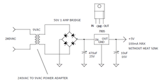
Simple 240VAC TO 5VDC POWER SUPPLY

This is simple way to power some 5v logic from a 240vac source. If a 120vac power adapter is used, the circuit will also work for 120vac power lines.
 
 
240VAC TO 5VDC POWER SUPPLY,

Monday, May 27, 2013

0 Comments
Posted in Arrangement, Art, Business

Simple Christmas star from multivibrator Circuit Diagram

This is so simple circuit But you can use this circuit as a Christmas star.Here I have used famous transistor 2N3904.If you are unable to find this transistor you can use D400 instead of that.This circuit operates with 9V.I used this circuit for the last Christmas If you used Blue color LED s It would give inexpressible attraction.


Note
# If you want to change the speed of this circuit You can do it by changing the values of 10uf and 100k
# This circuit can be operated with 9V power supply
# Fix this circuit on a pcb

Tuesday, April 30, 2013

0 Comments
Posted in Arrangement, Art, Business

Simple Telephone Record Control

This circuit will allow you to connect any tape recorder that has a mic and remote input to a phone line and automatically record both sides of a conversation when ever the phone is in use. You will need to take a couple of voltage readings before connecting the circuit. First determine the polarity of your phone line and connect it to the circuit as shown and then determine the polarity of the remote input and connect it to the circuit. Circuit operation is as follows. When the phone is on hook the voltage across the phone line is about 48volts dc. When the phone is off hook the voltage will drop to below 10volts dc. When the line voltage is at 48volts the FET is off which causes Q2 and Q3 to be off. When the phone is picked up the FET turns on along with Q2 and Q3 which turns your recorder on. The tape recorder must be in the record mode at all times. As you can see the power source for the circuit is the phone line.

Circuit Diagram

Saturday, April 13, 2013

0 Comments
Posted in Arrangement, Art, Business

Simple metal detector circuit diagram using CS209A

This simple metal detector circuit diagram is used to sense the presence of metal. A 100uH is used as a sensor. IC C209A has a build in oscillator circuit and the coil L1 form a part of its external LC circuit which determines the frequencies oscillation. When there is a presence of metals, the inductance of the coil is change and the resultant change in oscillation is demodulated to create an alarm. The LED also gives as a visual indicator. This circuit can sense metals up to a distance of few inches. Adjust the value of R1 POT to adjust the sensitivity.


Tuesday, April 9, 2013

0 Comments
Posted in Arrangement, Art, Business

A Simple NiCd Charger Circuit Diagram

A simple NiCd charger can be built using ‘junk box’ components and an inexpensive LM317 or 78xx voltage regulator. Using a current limiter composed of R3 and a transistor, it can charge as many cells as desired until a ‘fully charged’ voltage determined by the voltage regulator is reached, and it indicates whether it is charging or has reached the fully charged state. If the storage capacitor (C1) is omitted, pulsed charging takes place. In this mode, a higher charging current can be used, with all of the control characteristics remaining the same.
The operation of the circuit is quite simple. If the cells are not fully charged, a charging current flows freely from the voltage regulator, although it is limited by resistor R3 and transistor T1. The limit is set by the formula Imax ≈ (0.6 V) ÷ R3 For Imax = 200 mA, this yields R3 = 3 Ω. The LED is on if current limiting is active, which also means that the cells are not yet fully charged. The potential on the reference lead of the voltage regulator is raised by approximately 2.9 V due to the voltage across the LED.
Circuit Diagram :
A Simple Nicd Charger Circuit Diagram
 A Simple NiCd Charger Circuit Diagram
This leads to a requirement for a certain minimum number of cells. For an LM317, the voltage between the reference lead and the output is 1.25 V, which means at least three cells must be charged (3 × 1.45 V > 2.9 V + 1.25 V). For a 78xx with a voltage drop of around 3 V (plus 2.9 V), the minimum number is four cells. When the cells are almost fully charged, the current gradually drops, so the current limiter becomes inactive and the LED goes out.
In this state, the voltage on the reference lead of the regulator depends only on voltage divider R1/R2. For a 7805 regulator, the value of R2 is selected such that the current through it is 6 mA. Together with the current through the regulator (around 4 mA), this yields a current of around 10 mA through R1. If the voltage across R1 is 4 V (9 V – 5 V), this yields a value of 390 Ω. The end-of-charge voltage can thus be set to approximately 8.9 V. As the current through the regulator depends on the device manufacturer and the load, the value of R1 must be adjusted as necessary. The value of the storage capacitor must be matched to the selected charging current. As already mentioned, it can also be omitted for pulse charging.
Author: Wolfgang Schmidt   Copyright: Elektor

Sunday, April 7, 2013

0 Comments
Posted in Arrangement, Art, Business

Way to getting Simple Electrification Unit

The circuit is intended for carrying out harmless experiments with high-voltage pulses and functions in a similar way as an electrified fence generator. The p.r.f. (pulse repetition frequency) is determined by the time constant of network R1-C3 in the feedback loop of op amp IC1a: with values as specified, it is about 0.5 Hz. The stage following the op amp, IC1b, converts the rectangular signal into narrow pulses. Differentiating network R2-C4, in conjunction with the switching threshold of the Schmitt trigger inputs of IC1b, determines the pulse period, which here is about 1.5 ms. The output of IC1b is linked directly to the gate of thyristor THR1, so that this device is triggered by the pulses.

The requisite high voltage is generated with the aid of a small mains transformer, whose secondary winding is here used as the primary. This winding, in conjunction with C2, forms a resonant circuit. Capacitor C3 is charged to the supply voltage (12 V) via R3.When a pulse output by IC1b triggers the thyristor, the capacitor is discharged via the secondary winding. The energy stored in the capacitor is, however, not lost, but is stored in the magnetic field produced by the transformer when current flows through it. When the capacitor is discharged, the current ceases, whereupon the magnetic field collapses. This induces a counter e.m.f. in the transformer winding which opposes the voltage earlier applied to the transformer.

Simple Electrification Unit Circuit DiagramThis means that the direction of the current remains the same. However, capacitor C2 is now charged in the opposite sense, so that the potential across it is negative. When the magnetic field of the transformer has returned the stored energy to the capacitor, the direction of the current reverses, and the negatively charged capacitor is discharged via D1 and the secondary winding of the transformer. As soon as the capacitor begins to be discharged, there is no current through the thyristor, which therefore switches off. When C2 is discharged further, diode D1 is reverse-biased, so that the current loop to the transformer is broken, whereupon the capacitor is charged to 12 V again via R3. At the next pulse from IC1b, this process repeats itself.

Since the transformer after each discharge of the capacitor at its primary induces not only a primary, but also a secondary voltage, each triggering of the thyristor causes two closely spaced voltage pulses of opposite polarity. These induced voltages at the secondary, that is, the 230 V, winding, of the transformer are, owing to the higher turns ratio, much higher than those at the primary side and may reach several hundred volts. However, since the energy stored in capacitor C2 is relatively small (the current drain is only about 2mA), the output voltage cannot harm man or animal. It is sufficient, however, to cause a clearly discernible muscle convulsion.

    Total Pageviews